Series SD User’s Manual PID Controller and PID Profiling Controller TOTAL CUSTOMER CUS ER SATISF TISFACTI CTION 3 Year Warranty ISO 9001 Registered Company 1241 Bundy Boulevard., Winona, Minnesota USA 55987 Phone: +1 (507) 454-5300, Fax: +1 (507) 452-4507 http://www.watlow.com 0600-0041-0000 Rev. D April 2004 Winona, Minnesota USA Made in the U.S.A. $15.
Safety Information We use note, caution and warning symbols throughout this book to draw your attention to important operational and safety information. A “NOTE” marks a short message to alert you to an important detail. A “CAUTION” safety alert appears with information that is important for protecting your equipment and performance. Be especially careful to read and follow all cautions that apply to your application.
TC Table of Contents Chapter 1: Overview . . . . . . . . . . . . . . . . . . . . . . . . . .2 Chapter 2: Install and Wire . . . . . . . . . . . . . . . . . . . . .4 Dimensions . . . . . . . . . . . . . . . . . . . . . . . . . . . . . . .4 Installation . . . . . . . . . . . . . . . . . . . . . . . . . . . . . . . .6 Wiring . . . . . . . . . . . . . . . . . . . . . . . . . . . . . . . . . . .11 Chapter 3: Keys and Displays . . . . . . . . . . . . . . . . .20 Home Page Overview . . . . . . . . . . . . . . . .
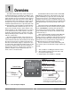
1 Overview Standard Series SD features include an IP65/NEMA 4X front panel rating; CE compliance, UL, CUL, CSA and NSF agency approvals; dual, four-digit displays in red or green**; autotuning for heat and cool outputs; ramp to set point, to gradually warm up your thermal system; and automatic/manual capability with bumpless transfer. A low-voltage model is also available.
Features and Benefits INFOSENSE™ Technology • Improves sensor accuracy by a minimum of 50%. User Definable Menu System • Simplifies operator interface User Definable Default Settings • Restores to user defined controller settings WATVIEW™ Software • Operation, configuration and data logging with a standard Windows® PC. Infrared Communications • Facilitates controller setup, operation and monitoring. Up to three outputs (1/32 DIN two outputs only) • Application versatility. • Configuration flexibility.
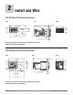
2 Install and Wire 1/32 DIN Series SD Controller Dimensions Front Top 53.6 mm (2.11 in) Back 97.8 mm (3.85 in) 45.0 to 45.6 mm (1.77 to 1.79 in) 8.6 mm (0.34 in) 47.2 mm (1.86 in) Ridges Panel Cutout 30.7 mm (1.21 in) Panel Thickness 1.5 to 9.5 mm (0.060 to 0.375 in) Tabs with Teeth 22.2 to 22.5 mm (0.87 to 0.89 in) 29.3 mm (1.15 in) 12.7 mm (0.50 in) minimum 12.7 mm (0.50 in) minimum Model Number Customer Front Panel 0.48 mm (0.
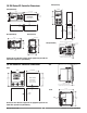
Front (vertical) 1/8 DIN Series SD Controller Dimensions Front (horizontal) 52.8 mm (2.08 in) 99.8 mm (3.93 in) 92.0 to 93.0 mm (3.62 to 3.65 in) Panel Cutout 52.8 mm (2.08 in) 45.0 to 45.6 mm (1.77 to 1.79 in) Panel Thickness 1.52 to 9.53 mm (0.060 to 0.375 in) 99.8 mm (3.93 in) 31.8 mm (1.25 in) minimum 7.9 mm (0.31 in) minimum RESET 7.9 mm (0.31 in) minimum Panel Cutout 31.8 mm (1.25 in) minimum Back (vertical) Back (horizontal) 92.0 to 93.0 mm (3.62 to 3.65 in) Panel Thickness 1.
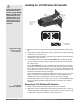
ç Caution: Follow the installation procedure exactly to guarantee a proper IP65/NEMA 4X seal. Make sure the gasket between the panel and the rim of the case is not twisted and is seated properly. Failure to do so could result in damage to equipment. Installing the 1/32 DIN Series SD Controller Panel Mounting Tab Mounting Bracket Mounting Ridge Gasket Bezel Arrows indicate the direction of pull to remove the connectors.
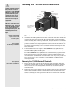
ç Installing the 1/16 DIN Series SD Controller Caution: Follow the installation procedure exactly to guarantee a proper IP65/NEMA 4X seal. Make sure the gasket between the panel and the rim of the case is not twisted and is seated properly. Failure to do so could result in damage to equipment. Note: Be careful not to overtighten the screws. This may cause the mounting bracket to fail. If the front bezel is touching the front panel, the mounting bracket is too tight.
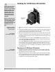
ç Installing the 1/8 DIN Series SD Controller Caution: Follow the installation procedure exactly to guarantee a proper IP65/NEMA 4X seal. Make sure the gasket between the panel and the rim of the case is not twisted and is seated properly. Failure to do so could result in damage to equipment. Note: Be careful not to overtighten the screws. This may cause the mounting bracket to fail. If the front bezel is touching the front panel, the mounting bracket is too tight.
ç Caution: Follow the installation procedure exactly to guarantee a proper IP65/NEMA 4X seal. Make sure the gasket between the panel and the rim of the case is not twisted and is seated properly. Failure to do so could result in damage to equipment. Note: Be careful not to overtighten the screws. This may cause the mounting bracket to fail. If the front bezel is touching the front panel, the mounting bracket is too tight. Installing and mounting requires access to the back of the panel.
Series SD Family — Back Views in Scale NOTE: The SD model number determines which diagram applies to your unit. 5 6 7 8 9 10 11 12 13 14 1 2 3 4 5 6 12 13 14 1 2 3 4 Figure 10a — 1/32 DIN with a Universal Process Output installed for output 1 (S D 3 _ - _ F _ _ - _ _ _ _). 1 2 3 4 8 9 1011 5 6 7 8 9 10 11 1 2 3 4 5 6 8 9 1011 Figure 10b — 1/32 DIN with other than a Universal Process Output installed for output 1 (S D 3 _ - _ (C,K or J) _ _ - _ _ _ _).
Ó Warning: Use National Electric (NEC) or other country-specific standard wiring and safety practices when wiring and connecting this controller to a power source and to electrical sensors or peripheral devices. Failure to do so may result in damage to equipment and property, and/or injury or loss of life. Note: To prevent ground loops, isolation needs to be maintained from input to output when using switched DC or analog process outputs.
ç (all model numbers) Thermocouples are polarity sensitive. The negative lead (usually red) must be connected to terminal 11. • Input impedance: >20 MΩ 4 8 9 1011 +10 -11 10 11 5 6 7 8 9 10 11 6 Warning: Use National Electric (NEC) or other country-specific standard wiring and safety practices when wiring and connecting this controller to a power source and to electrical sensors or peripheral devices. Failure to do so may result in damage to equipment and property, and/or injury or loss of life.
ç (all model numbers) • Input impedance 100 Ω, dc only. • Controller does not supply power for the current loop. 4 Warning: Use National Electric (NEC) or other country-specific standard wiring and safety practices when wiring and connecting this controller to a power source and to electrical sensors or peripheral devices. Failure to do so may result in damage to equipment and property, and/or injury or loss of life. Watlow carries the R.C.
ç Figure 14a — Output 1 Switched DC Warning: Use National Electric (NEC) or other country-specific standard wiring and safety practices when wiring and connecting this controller to a power source and to electrical sensors or peripheral devices. Failure to do so may result in damage to equipment and property, and/or injury or loss of life. • Supply current 30 mAÎ (dc) maximum. • Not recommended for switching mechanical relays. • Output supplies power.
ç Figure 15a — Output 2 Solid-state Relay Warning: Use National Electric (NEC) or other country-specific standard wiring and safety practices when wiring and connecting this controller to a power source and to electrical sensors or peripheral devices. Failure to do so may result in damage to equipment and property, and/or injury or loss of life. • Form A contact SD_ _ - _ _ K _ - _ _ _ _ • 0.5 A maximum, resistive • 20 VA pilot duty, 120/240VÅ (ac), inductive • See Quencharc note. • 24 to 240VÅ (ac).
ç Figure 16a — Output 3 Mechanical Relay Warning: Use National Electric (NEC) or other country-specific standard wiring and safety practices when wiring and connecting this controller to a power source and to electrical sensors or peripheral devices. Failure to do so may result in damage to equipment and property, and/or injury or loss of life. • Form A contact SD_ _ - _ _ _ E - _ _ _ _ • 5 A, resistive • 125 VA pilot duty, 120/240VÅ (ac), inductive • See Quencharc note. • 240VÅ (ac) maximum.
ç Figure 17a — Output 3 Open Collector Warning: Use National Electric (NEC) or other country-specific standard wiring and safety practices when wiring and connecting this controller to a power source and to electrical sensors or peripheral devices. Failure to do so may result in damage to equipment and property, and/or injury or loss of life. • Maximum current sink 250 mAÎ (dc). SD_ _ - _ _ _ C - _ _ _ _ • Maximum supply voltage 42VÎ (dc). • For inductive loads, see Quencharc note.
Selecting an EIA/TIA-232 to EIA/TIA-485 Converter 12 V GN ( GND dc) TD D ( TD B) (A ) When choosing an EIA/TIA 232 to 485 converter, look for one with the following features: Two-wire capability EIA/TIA-485 can be implemented as a two-wire system or a four-wire system. Most Watlow controllers, including the Series SD, use two-wire communications when working with EIA/TIA-485. The converter selected must have a two-wire mode. Some converters can only be used in a four-wire mode.
Ethernet Gateway The EM00-GATE-0000 is a bridge that allows up to 32 Watlow controllers to be directly connected to an Ethernet network. The gateway provides a bridge for Modbus messages between the Ethernet bus and EIA-485 or EIA-232 links. The Gateway supports full product configuration monitoring and configuration of runtime parameters via MODBUS TCP over TCP/IP using a software package such as Watlow’s WATVIEW™. The Series SD can be configured using WATVIEW with or without the EM Gateway.
3 Keys and Displays 1/32 DIN 2 SD SD SD 1 1/8 DIN Horizontal 1/16 DIN 1 % 2 3 % 1 1/8 DIN Vertical 2 3 1/4 DIN SD 1 2 3 % SD4 1 % 2 3 % SD4 1 2 3 % Upper Display (Left Display on 1/32 DIN): Indicates the process in the Home Page, or the value of the parameter in the lower display in other pages. Lower Display (Right Display on 1/32 DIN): Indicates the set point or output power value during operation, or the parameter whose value appears in the upper display.
Home Page Overview Adjusting the temperature set point The Home Page is the default display of the Series SD controller. The process value is usually shown in the upper display. Press Infinity Key ˆ to return to Home Page from any page or parameter. Adjust the temperature set point in the Home Page. It is not necessary to enter any other page. The temperature set point appears in the lower display and only appears when the controller is in the automatic mode.
Operations Page Overview The Operations Page contains parameters accessed during normal day-to-day operation. The Series SD provides a patented user-definable menu system, allowing the user to customize the Operations Page contents. To go to the Operations Page, press the Advance Key ‰ once from the Home Page. • Press the Advance Key ‰ to move through the parameter prompts. At the end of the Operations Page parameters, press the Infinity Key ˆ to return to the Home Page.
Setup Page Overview [`SEt] [PAgE] The Setup Page contains parameters that define basic controller functions. Go to the Setup Page for initial configuration or if your application requirements change. Be sure to program the Setup Page first! Always press the Infinity Key ˆ to return to the Home Page. You must start from the Home Page. To go to the Setup Page, press both the Up ¿ and Down ¯ keys for about three seconds. • Press the Advance Key ‰ to move through the parameter prompts.
Programming Page Overview [Prog] [PAgE] The Programming Page determines what parameters the user wants to appear on the Operations Page. Select a parameter for any of the 20** (23 for the profiling version***) Programming Page locations, P1 to P20 (P23***). These now appear on the Operations Page. All 20** (23***) locations have parameters selected as defaults. To go to the Programming Page, hold down the Infinity key ˆ, then press the Advance Key ‰, and hold both down for about six seconds.
4 Home Page Press the Infinity Key ˆ at any time to go to the Home Page. Depending upon the controller’s status, you will see some combination of the parameters listed below. Normally, you will see the Process Value in the upper display and the Set Point in the lower display. See Home Page Overview in Chapter Three. After 60 seconds with no key presses, the controller reverts to the Home Page.
5 Setup Page To go to the Setup Page, press both the Up ¿ and Down ¯ keys for three seconds from the Home Page. [`SEt] will appear in the upper display and [PAgE] will appear in the lower display. • Press the Advance Key ‰ to move through the parameter prompts. • Press the Up ¿ or Down ¯ keys to change the parameter value. • Press the Infinity Key ˆ at any time to return to the Home Page display. Display Parameter Name Description Settings Range (Integer values for Modbus in parentheses.
Display [Sc;Lo] [Sc.Lo] [Sc;hi] [Sc.hi] [P1;LE] [P1.LE] Parameter Name Description Process Scale Low Set the low scale for process inputs. Process Scale High Set the high scale for process inputs. Process Input Low Error Set the low process value that will cause an error to occur for the process input. Settings Range (Integer values for Modbus in parentheses.) Default Modbus* Appears if: (less 40,001 offset) Read/Write 0.00 to 20.00 mA: if [`Sen] 4.00 mA is set to [`mA] (0000 to 20000) 0.
Display [SP;Lo] [SP.Lo] [sP;hi] [SP.hi] Parameter Name Description Set Point Low Limit Set the low range for the set point. Set Point High Limit Set the high range for the set point. Settings Range (Integer values for Modbus in parentheses.) Default Modbus* Appears if: (less 40,001 offset) Read/Write Min. operating range (of sensor) to [SP;Hi] -0.100: if {`sen} is set to {``tc} Min. operat- *240, 241 Always active. ing range (J R/W (thertype): {``tc} mocouple) -328 to [SP;hi] -0.
Display Parameter Name Description Settings Range (Integer values for Modbus in parentheses.) Default Modbus* Appears if: (less 40,001 offset) Read/Write [PL`1] [PL 1] Power Limit 1 Set the maximum power output for a control output 0.0 to 100.0% power 100.0% (000 to 10000) (Two decimal places implied for Modbus.) 160 R/W [Ot`1] is set to [hEAt] or [CooL]. [PsL1] [PSL1] Output Power Scale Low 1 Set the low end of the range within which the output will scale. 0.0 to 100.
Display Parameter Name Description Settings Range (Integer values for Modbus in parentheses.) Default Modbus* Appears if: (less 40,001 offset) Read/Write [r1;C ; O] [r1.CO] Output 1 Retransmit Offset Set the high scale for the process output. -999.0 to 999.0 (-999000 to 999000) 0 *310, 311 R/W Output 1 is a process output (SD_ _ - _ _ _ F _ _ _ _ ) and [Ot`1] is set to [rmt] . [Ot`2] [Ot 2] Output 2 Function Set Output 2 function.
Display Parameter Name Description Settings Range (Integer values for Modbus in parentheses.) Default Modbus* Appears if: (less 40,001 offset) Read/Write [Ctr3] [Ctr3] Control Method 3 Set Output 3 control type. This parameter is only used with PID control, but can be set anytime. [`Ftb] Fixed Time Base (0) [Urtb] Variable Time Base (1) [Ftb3] [Ftb3] Fixed Time Base 3 (Cycle Time) Set the time base for Fixed Time Base Control. 1.0 to 60.0 seconds if Output 20.0: mech.
Display Parameter Name Description Settings Range (Integer values for Modbus in parentheses.) Default Modbus* Appears if: (less 40,001 offset) Read/Write [r3;lo] [r3.Lo] Output 3 Retransmit Low Scale Set the low scale for the retransmit output. -1999.0 to 9999.0 (-1999000 to 9999000) 0 *316, 317 R/W Output 3 is a process output (SD_ _ - _ _ _ F _ _ _ _ ) and [Ot`3] is set to [rmt] . [r3;h ; i] [r3.hi] Output 3 Retransmit High Scale Set the high scale for the retransmit output. -1999.
Display Parameter Name Description Settings Range (Integer values for Modbus in parentheses.) Default Modbus* Appears if: (less 40,001 offset) Read/Write [hyS3] [hyS3] Alarm 3 Hysteresis Set the hysteresis for an alarm. This determines how far into the safe region the input needs to move before the alarm can be cleared. 0.0 to 999.0 (0000 to 999000) 1.000 *136, 137 R/W [Ot`3] is set to [dE;AL] or [Pr;AL]. [Lgc3] [Lgc3] Alarm 3 Logic Select the alarm output condition in the alarm state.
Display Parameter Name Description Settings Range (Integer values for Modbus in parentheses.) Default Modbus* Appears if: (less 40,001 offset) Read/Write [rP;Sc] [rP.Sc] Ramp Scale** Select the scale of the ramp rate. [hour] degrees/hour (0) [Min] degrees/minute (1) [hour] (0) 267 R/W [``rP] is set to [`Str] or [``On]. [rP;rt] [rP.rt] Ramp Rate** Set the rate for the set point ramp. 0 to 9999 (0000 to 9999000) 100 *268, 269 R/W [``rP] is set to [`Str] or [``On].
6 Operations Parameters Table These parameters can be selected to appear in the Operations Page. Select parameters to appear in the Operations Page in the Programming Page. Press the Advance Key ‰ to enter the Operations Page and to step through the parameters. For Profiling controller, set [Prog] to [~~no] to access the Operations Page. Press the Infinity Key ˆ to return to the Home Page at any time. Note: The Operations Page is not accessible when a profile is running.
Display [rA;ht] [rA.ht] Parameter Name Description Settings Range (Integer values for Modbus in parentheses.) Rate Heat Set the PID rate time in minutes for the heat output. 0.00 to 9.99 minutes (0000 to 9990) Derivative Heat Set the PID derivative time in minutes for the heat outputs. 0.00 to 9.99 minutes (0000 to 9990) [dB;ht] [dB.ht] Dead Band Heat An offset of the heating proportional band from the set point. [h;hyS] Default Modbus* Appears if: (less 40,001 offset) Read/Write 0.
Display [rA;Cl] [rA.CL] Parameter Name Description Settings Range (Integer values for Modbus in parentheses.) Rate Cool Set the PID rate time in minutes for the cool outputs. 0.00 to 9.99 minutes (0000 to 99990) Derivative Cool Set the PID derivative time in minutes for the cool outputs. 0.00 to 9.99 minutes (0000 to 99990) [dB;Cl] [db.CL] Dead Band Cool An offset of the cooling proportional band from the set point. [C;hyS] Cool Hysteresis Set the control switching hysteresis for on/off control.
Display [A1;hi] [A1.hi] Parameter Name Description Alarm 1 High Set the high alarm set point. Settings Range (Integer values for Modbus in parentheses.
7 Programming Page The Programming Page allows you to select what parameters appear on the Operations Page. To go to the Programming Page, press the Advance ‰ and Infinity ˆ keys for six seconds from the Home Page. {Prog} will appear in the upper display and {page} in the lower display. • Press the ‰ Advance Key to move through the parameter prompts. • Press the Up ¿ or Down ¯ keys to change the parameter value. • Press the Infinity Key ˆ at any time to return to the Home Page.
Programming Page Example An oven manufacturer wants users of their ovens to have easy access to the Series SD PID parameters. They also want to limit access to other parameters they do not want them to change. This can be achieved by customizing the Operations Page. The Programming Page configuration determines which parameters appear on the Operations Page. The static set point version (SD_C-_ _ _ _- _ _ _ _.) has 20 Programming Page locations, P1 to P20. The profiling version (SD_R-_ _ _ _- _ _ _ _.
8 Profiling Page The Profiling Page allows you to enter your ramp and soak profile information. To go to the Profiling Page from the Home Page, press the Advance ‰ and [Prof] appears in the lower display. Press the Up ¿ key to change the upper display to [~yes]. • Press the ‰ Advance Key to move through the profile parameter prompts. • Press the Up ¿ or Down ¯ keys to change the profile parameter values. • Press the Infinity Key ˆ at any time to return to the Home Page.
Display Parameter Name Description Settings Range (Integer values for Modbus in parentheses.) Default Modbus* Appears if: (less 40,001 offset) Read/Write [StYp] Set Point Step -1999 to 9999 75 (-1999000 to 9999000) Target set point values must be between [SP;Lo] to [SP;Hi] or step will fail the Pre-Run check and will not run. See page 53. Profiling version only. [tg.SP} Target Set Point Indicates ending set point value the controller ramps to during the set point step.
Display Parameter Name Description Settings Range (Integer values for Modbus in parentheses.) Default Modbus* Appears if: (less 40,001 offset) Read/Write [Soah] Soak Step [hour] [hour} [Min] [Min} [~SEC] [ SEC} [Ent1] [Ent1} [Ent2] [Ent2} [Ent3] [Ent3} [WF;P] [WF.P} [WPr] [WPr} Hours The number of hours, (plus Min and Sec parameters) equal the total soak step time at set point under the [soaH] step type.
Display Parameter Name Description Settings Range (Integer values for Modbus in parentheses.) Default Modbus* Appears if: (less 40,001 offset) Read/Write [~~JL] Jump Loop Step [~~JF] [ JF] [~~JS] [ JS] [~~JC] [ JC] Jump File Selects the file which is to be jumped to. This is a zero-time step. 1 to 4 Jump Step Selects the step which is to be jumped to. This is a zero-time step. 1 to 10 Jump Count Indicates the number of times the jump is to be done. A value of 0 results in an infinite loop.
How to Navigate the Profiling Menus Pre-Run Menu Profile Off Pre-Run Menu Profile Run or Hold Menu function Start a profile. Holding, resuming or stop- Programming a profile. ping a profile. Viewing profile status. Enter menu Press the Infinity ˆ key. Press the Infinity ˆ key. Press the Advance ‰ key. At the [Prof] prompt, select [~yes]. Press the Advance ‰ key. Scroll through menu Press the Advance ‰ key. N/A Press the Advance ‰ key. Press the Advance ‰ key.
Run Menu* The Run Menu is active when a program is running. Enter the Run Menu by pressing the Advance ‰ key once from the Home Page. The profile indicator light will be lit when in the Run Mode. The file-step [~F;st] prompt is visible in the Run Menu and shows the current file and step number of the running profile. Other prompts in the Run menu show the target end set point, as well as status for time remaining, ramp rate, wait-for, event status and jump count if relevant.
menu. Selecting [~Off] in the upper display will stop the profile and move the set point to [~Off]. To resume a profile on hold: 1. You must start from the Home Page. Press the Infinity ˆ key to exit a menu and return to the Home Page. Press the Infinity ˆ key to enter the Pre-Run menu. [SelC] will appear in the lower display. 2. Use the Up ¿ or Down ¯ key to select [resU] in the upper display. The profile will continue starting with the step it was running when it was placed on hold.
Jump-loop Step A profile can jump forward or backwards from any step, except Step 1 of any file. You cannot jump-loop to the step that you are on. Jump-loop example: Step 1 [Stpt] Set Point Step Step 2 [Stpt] Set Point Step Step 3 [Soah] Soak Step Step 4 [Stpt] Set Point Step Step 5 [~~JL] Jump-loop [~~JF] = 1 [~~JS] = 2 [~~JC] = 1 Step 6 [~End] End In this example the program will execute steps 2 through 4 a total of 2 times. This includes the initial pass and the pass associated with the Jump Count of 1.
Example profile Gwen, of Smith Manufacturing needs to perform a burn-in test of their product in an environmental chamber. The test should take the product through the following sequence: 1. Heat from room temperature to a temperature of 150 degrees F over a 1-hour period. 2. Hold the temperature at 150 degrees F for 2 hours. 3. Cool the temperature to 32 degrees F as quickly as possible. 4. Once the temperature reaches 32 degrees F, hold that temperature for 2 hours. 5.
Circle File Number: 1 2 3 4 Master Step Chart (make a copy and write in your settings) Step 1 ___ Stpt (Ptyp=ti) ___ Stpt (Ptyp=rate) ___ Soak ___ JL ___ LFil ___ End Tg.SP Tg.SP Hour JF LF End: Off Hold Hour Rate Min. JS Min. Sec. Ent1: On Off Ent2: On Off Ent3: On Off Ent1: On Off Ent2: On Off Ent3: On Off Sec. Ent1: On Off Ent2: On Off Ent3: On Off WF.P Yes No JC Step 2 ___ Stpt (Ptyp=ti) ___ Stpt (Ptyp=rate) ___ Soak ___ JL ___ LFil ___ End Tg.SP Tg.SP Hour JF LF End: Off Hold Hour Rate Min.
Series SD Profiling Modbus Registers This section contains information for creating, editing and running profiles using Modbus. Some of these are available only through Modbus and others can be accessed through the front panel and Modbus. If a parameter is accessible only through Modbus, N/A appears in the display column. Parameters appear in profiling version only. Display Parameter Name Description Settings Range (Integer values for Modbus in parentheses.
Monitoring Profile Status from Modbus Display Parameter Name Description Settings Range (Integer values for Modbus in parentheses.) Default Modbus* Appears if: (less 40,001 offset) Read/Write N/A File Running File number that is currently running. 1 to 4 1 900 R Profile is running. N/A Step Running Step number that is currently running. 1 to 10 1 901 R Profile is running. [EnSP] [EnSP] End Set Point Value Set point value reached at the end of the current step.
Series SD Profiling Modbus Register Numbers This table contains the Modbus register numbers. The number in ( ) identifies the file number for that register.
9 Factory Page To go to the Factory Page, press both the Up ¿ and Down ¯ keys for six seconds from the Home Page. {Fact} will appear in the upper display and {page} in the lower display. • Press the ‰ Advance Key to move through the parameter prompts. • Press the Up ¿ or Down ¯ keys to change the parameter value. • Press the Infinity Key ˆ at any time to return to the Home Page. Display [AMb] [AMb] [A;mn] [A.Mn] [A;ma] [A.MA] [DSPL] [dSPL] [rESt] [rESt] [Usr;r] [Usr.r] [USr;S] [USr.
Display [O;ty1] Parameter Name Description Settings Range (Integer values for Modbus in parentheses.) Default Modbus* Appears if: (less 40,001 offset) Read/Write Output 1 Type Displays the hardware type for Output 1. [nonE] none (0) [none] (0) [~~DC] DC/open collect. (1) [rLAY] mech. relay (2) [~SSr] solid-state relay (3) [Proc] process (4) 202 R Always active. Output 2 Type Displays the hardware type for Output 2. [nonE] none (0) [~~DC] DC/open collect. (1) [rLAY] mech.
10 Features Saving and Restoring User Settings . . . . . . . . . . . . . . . . . . . . . .57 Saving and Restoring User Profiles . . . . . . . . . . . . . . . . . . . . . .57 Operations Page . . . . . . . . . . . . . . . . . . . . . . . . . . . . . . . . . . . . . .57 Autotuning . . . . . . . . . . . . . . . . . . . . . . . . . . . . . . . . . . . . . . . . . . .58 Manual Tuning . . . . . . . . . . . . . . . . . . . . . . . . . . . . . . . . . . . . . . . .58 Inputs . . . . . . . . . . . . . . . . . . . . .
Saving and Restoring User Settings Recording setup and operations parameter settings for future reference is very important. If you unintentionally change these, you will need to program the correct settings back into the controller to return the equipment to operational condition. After you program the controller and verify proper operation, use [USr;S] to save the settings into a special section of memory.
Press the Advance Key ‰ once to go to the first selection in the page. The parameter choices will appear in the top display and the selection number will appear in the bottom display. Use the Up ¿ or the Down ¯ key to change the selected parameter in the top display. If you do not want a parameter to appear for that location, select [nonE].
Calibration Offset Sensor Selection Calibration offset allows a device to compensate for an inaccurate sensor, lead resistance or other factors that affect the input value. A positive offset increases the input value, and a negative offset decreases the input value. The input offset value can be viewed or changed with Calibration Offset [`CAL] (Operations parameters). You need to configure the controller to match the input device, which is normally a thermocouple, RTD or process transmitter.
High Scale and Low Scale When an analog input is selected as process voltage or process current input, you must choose the value of voltage or current to be the low and high ends. For example, when using a 4 to 20 mA input, the scale low value would be 4.00 mA and the scale high value would be 20.00 mA. Commonly used scale ranges are: 0 to 20 mA, 4 to 20 mA, 0 to 5V, 1 to 5V and 0 to 10V. The Series SD allows you to create a scale range for special applications other than the standard ones listed above.
On-Off Control On-off control switches the output either full on or full off, depending on the input, set point and hysteresis values. The hysteresis value indicates the amount the process value must deviate from the set point to turn on the output. Increasing the value decreases the number of times the output will cycle. Decreasing hysteresis improves controllability.
The droop caused by proportional control can be corrected by adding integral (reset) control. When the system settles down, the integral value is tuned to bring the temperature or process value closer to the set point. Integral determines the speed of the correction, but this may increase the overshoot at startup or when the set point is changed. Too much integral action will make the system unstable. Integral is cleared when the process value is outside of the proportional band.
Curve 1 is for oil cooled extruders and curve 2 is for water cooled extruders. Change the linearity for each output with Output Non-linear Function 1, 2 or 3 ([nLf1], [nlf2] or [nlf3]) in the Setup Page. 100 Actual Output Power would result in an actual output power level of 50%. But if the PID calculated power output is 100%, then the power level will be 70%. Power scaling establishes the maximum power output and the minimum power output. The output power is then linearly scaled within that range.
Temperature Set Point Temperature reaches Set Point quickly Time Set Point Temperature put is distributed in groupings of three ac line cycles. For each group of three ac line cycles, the controller decides whether the power should be on or off. There is no fixed cycle time since the decision is made for each group of cycles.
Alarm Hysteresis Alarm Silencing An alarm state is triggered when the process value reaches the alarm high or alarm low set point. Alarm hysteresis defines how far the process must return into the normal operating range before the alarm can be cleared. Alarm hysteresis is a zone inside each alarm set point. This zone is defined by adding the hysteresis value to the alarm low set point or subtracting the hysteresis value from the alarm high set point.
485 option directly supports communication with up to 32 devices on a network or up to 247 devices using a 485 repeater. Basic communications settings must first be configured on the controller in the Setup Page. Match the Baud Rate [baUd] to that of the computer and select a unique Address [Addr] for each Series SD. To view or change controller settings with a personal computer, you need to run software that uses the Modbus RTU protocol to read or write to registers in the controller.
6. Test the communications. Once communications is configured, test the link to the controller for verification that everything is wired and configured properly. Check the wiring and configurations if things aren’t working. One misplaced wire or one incorrect setting will keep communications from working.
Troubleshooting Indication Probable Cause(s) Corrective Action No power. Controller appears dead. No display indication in either window. Power to unit may be off. Fuse may be blown. Breaker may be tripped. Safety interlock door switch, etc. may be activated. Separate system limit control may be latched. Wiring may be open. Input power may be incorrect. Check switches, fuses, breakers, interlocks, limit devices, connectors, etc. for energized condition and proper connection.
Troubleshooting Indication Probable Cause(s) Corrective Action Getting alarm message [A1hi], [A2hi], [A3hi], [A1Lo], [A2Lo] or [A3Lo]. The process value is beyond an alarm set point. Determine when alarms messages will display and the proper response to an alarm message. Alarm is occurring when it should not. Alarm settings are incorrect. Adjust the alarm settings to be correct for the application. Input may be in an error condition. See error messages. Alarm may be latched.
Troubleshooting Indication Probable Cause(s) Corrective Action Profile will not start. or resume. Lower display flashes between static set point value and File Number / Step Number. For example, if File 1, Step 1 is not valid, the display will flash 1.1 Profile step has target set point or Wait-for Process values that are outside of [SP;lo] or [SP;hi] values. Jump Loop step is trying to jump to itself. Keep target set point or Wait-for Process values inside set point limits or adjust set point limits.
A Appendix Specifications • (2396) Controller • • • • • • • • • • Microprocessor-based, user-selectable control modes Heat and cool autotune for control outputs 1 Universal input, 3 outputs (2 outputs on 1/32 DIN) Control outputs user-selectable as on-off, P, PI, PID Display update: 10 Hz, adjustable digital filter Output update: burst, 0.1 to 999.
• • • • • • • • Solid-state Relay Optically isolated Zero cross switched Without contact suppression Minimum load current: 10 mA rms Maximum current: 0.
Ordering Information and Model Numbers (2397) S DIN Sizes 3, 6, 8, 9 or 4 3 1/32 DIN 6 1/16 DIN 8 1/8 DIN Vertical 9 1/8 DIN Horizontal 4 1/4 DIN Control Type C or R* C R PID Control D — — A Profiling PID Control Power Supply H or L H 100 to 240VÅ (ac) L 24V‡ (ac/dc) Output 1 C, K, F or J C Switched DC K Solid-state Relay Form A, 0.5 Amp F Universal Process J Mechanical Relay Form A, 2 Amp Output 2 A, C, K, J or U A None C Switched DC K Solid-state Relay Form A, 0.
Index 1/16 DIN 20 1/32 DIN 20 1/8 DIN Horizontal 20 1/8 DIN Vertical 20 Access Lockout 59 AC Line Frequency 23, 33, 64 Active Displays 23, 33, 68 Active Output Indicator Lights 20 Address 23, 34, 39, 66 Adjust the set point 21 Adjusting the set temperature 21 Advance Key 20 Advanced Control Algorithm 3 Agency Approvals 1, 72 Alarm 1 Hysteresis 23, 32 Alarm 1 Latching 23, 32 Alarm 1 Logic 23, 32 Alarm 1 Message 23, 32 Alarm 1 Silencing 23, 32 Alarm 1, 2, or 3 Silencing 64 Alarm 2 Hysteresis 23, 32 Alarm 2 La
NEMA 4X 7 Non-latching Alarm 32, 33, 69 Non-latching Input Error 23, 33, 60 Non-linear output curve 29, 30, 31, 63 Non-volatile memory writes 67 On-Off Control 61, 69 Open Loop 60 Open Loop Output Power 25 Operating Environment 72 Operating Ranges 71 Operations Page 3, 22, 24, 35, 40, 57, 69 Operations Page Overview 22 Operations Parameters Table 35 Operator Interface 71 Ordering Information 73 Output Non-linear Function 1 23, 29, 63 Output Non-linear Function 2 23, 30, 63 Output Non-linear Function 3 23, 3
Prompt Index [`A;16] 24 [A1;hi] 22, 25, 38, 39 [A1;Lo] 21, 22, 25, 38, 39 [A2;hi] 22, 25, 38, 39 [A2;Lo] 22, 25, 38, 39 [A3;hi] 22, 25, 38, 39 [A3;Lo] 22, 25, 38, 39 [A;ma] 24, 54 [A;mn] 24, 54 [A;Ot1] 24, 54 [A;Ot3] 24, 54 [ACLF] 23, 33 [Addr] 23, 34, 39, 40, 66 [AMb] 24, 54 [AO1;U] 23, 29 [AO3;U] 23, 31 [`Aut] 22, 35, 39, 58 [bAud] 23, 34, 66 [`C-F] 23, 26, 39 [`CAL] 22, 35, 39, 59 [CL;m] 22, 36, 39, 60, 69 [Cntl] 25, 27 [Ctr1] 23, 28 [Ctr2] 23, 30 [Ctr3] 23, 31 [db;CL] 37, 39, 62 [dB;ht] 36, 39, 62 [``dE
Declaration of Conformity Series SD Watlow Winona, Inc. 1241 Bundy Blvd.
How to Reach Us Your Authorized Watlow Distributor: TOTAL CUSTOMER CUS ER SATISF TISFACTI CTION 3 Year Warranty Corporate Headquarters in the U.S.: Watlow Electric Manufacturing Co. 12001 Lackland Road St. Louis, Missouri, USA 63146 Telephone: +1 (314) 878-4600 Fax: +1 (314) 878-6814 Europe: Watlow GmbH Industriegebiet Heidig Lauchwasenstr. 1, Postfach 1165 Kronau 76709 Germany Telephone: +49 -7253-9400-0 Fax: +49 -7253-9400-44 Watlow France S.A.R.L.