Series 982 User’s Manual Includes 981, 982, 983 and 984 1/8 DIN Microprocessor-Based, Ramping Controller User Levels: • New User............................................go to page 1.1 • Experienced User ...............................go to page 2.1 • Expert User.........................................go to page 4.1 Installers: • Set-up .................................................go to page 1.3 • Wiring & Installation............................go to page 2.
About This Manual How to Use this Manual We have designed this user’s manual to be a helpful guide to your new Watlow controller. The headlines in the upper right and left corners indicate which tasks are explained on that page. If you are a new user, we suggest that your read through the whole manual. If you are experienced, you may want to begin reading on page 2.1.
Table of Contents WATLOW Series 982 User’s Manual Chapter 1 Starting Out With the Watlow Series 981/982 1.1 Starting Out With the Watlow Series 981/982 1.2 Menu Overview 1.3 DIP Switch Locations and Functions 1.4 Setting the Hardware Lockout DIP Switch 1.5 External Power Supply DIP Switches 1.6 Input Type DIP Switches Chapter 2 Install and Wire the Series 981/982 2.1 Panel Cutout 2.1 Dimensions 2.2 Installation Procedure 2.3 Wiring the Series 981/982 2.4 I/O Isolation 2.4 Power Wiring 2.
Notes iv WATLOW Series 982 User’s Manual Contents
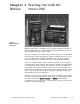
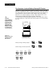
Chapter 1 Starting Out with the Watlow Series 982 Figure 1.1 Watlow Ramping Controllers. Watlow’s Series 982, a 1/8 DIN microprocessor-based ramping controller, is truly an innovation in the controller field. The Series 982 provides 6-step program capability, with up to 4 files possible. The new controller meets a wide variety of needs in the process industries. Its broad range of I/O options allows control of virtually any process variable.
Menu Overview Display Loop (Lower Display) Press ∂ to exit any menu and reach the Display Loop at any time. ˜ NOTE: This is a complete listing of all Series 982 prompts. Not all prompts will appear on your control. They are dependent on your configuration and model number. To navigate: Press ∂ to return to the Display Loop from any location and to advance through the Display Loop. Press > or < to move between the menus.
DIP Switches DIP Switch Locations and Functions The Series 982 has several Dual In-line Package (DIP) Switches inside the control. Depending on your model number, your unit can have as few as one DIP switch or as many as five DIP switches. Use the rest of this chapter as a DIP switch reference guide. To set any DIP switch: 1. Remove the control chassis from the case. Release the two tabs on one side of the bezel, by pressing in firmly on each until you hear the tab snap.
DIP Switches The Hardware Lockout/Battery Backup DIP Switch ç CAUTION: There is danger of an explosion if the battery is incorrectly replaced. This battery is factory replaceable only. Dispose of used batteries according to manufacturer’s recommendations. All units are equipped with a DIP switch for hardware lockout of the SEt and Fcty prompt menus, and to enable battery backup of the Run parameters. The location of the board and switch appear below.
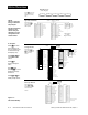
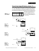
DIP Switches External Power Supply DIP Switches (Option “T”) Table 1.5 Power Supply DIP Switch Settings. Models equipped with an external signal conditioner power supply (Option “T”), have a DIP switch for selecting the power supply voltage. Output 2, 3 or 4 can be ordered with the external power supply. The location of each board and DIP switch appear below. When the control leaves the factory, both switches are off. The figures below show a PC board cutaway for each DIP switch.
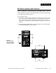
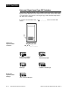
DIP Switches Universal Signal Input Type DIP Switches Remove the chassis from the case. Looking at the back of the control, the input #1 (In1) switch is located at the base of the unit. Set the DIP switches to match the appropriate sensor input types will automatically match the DIP switch settings. If you have model number 98_ Cswitch. Figure 1.6a Input DIP Switch Locations.
Chapter 2 Installation and Wiring ˜ WATL W 4.03" (102mm) NOTE: Space panel cutouts at least 1.66 inches (42.2mm) apart. PROCESS WATL W L1 L2 DEV % OUT L3 L4 DSPY 4.03" (102mm) 2.18" (55 mm) PROCESS DISPLAY HOLD RUN ˜ L1 L2 L3 DEV HOLD % OUT RUN SERIES 989 L4 MODE SERIES 988 NOTE: Adjustable mounting brackets can be side-mounted. 2.18" (55 mm) Adjustable Mounting Bracket Panel ˜ Panel Cutout Maximum Panel Thickness 0.38" (9.
Installation Installing the Series 982 Installing and mounting requires access to the back of the panel. 1. Make a panel cutout. 2. To remove the controller chassis from its case, press in firmly on the two tabs on one side or the top of the bezel until they unsnap, then unsnap the two tabs on the opposite side or the bottom. Pull the chassis out of the case by gently rocking it. ˜ NOTE: Removing the controller chassis from its case makes mounting easier. 3. Slide the case into the panel cutout.
Installation ç CAUTION: Follow the installation procedure exactly to guarantee a proper NEMA 4X seal. Make sure the gasket between the panel and the rim of the case is not twisted and is seated properly. Failure to do so could result in damage to equipment. 4. Loosen the mounting bracket screws enough to allow for the mounting collar and panel thickness. Place each mounting bracket into the mounting slots (head of the screw facing the back of the controller).
Wiring Wiring the Series 982 ∫ WARNING: To avoid potential electric shock, use National Electric Code (NEC) safety practices when wiring and connecting this unit to a power source and to electrical sensors or peripheral devices. Failure to do so could result in injury or death. ˜ NOTE: Input-to-output isolation is defeated when the external signal conditioner power supply option is used to power a transmitter connected to input 1. Wiring options depend on the model number and DIP switch settings.
Wiring Wiring 0-20 and 4-20mA Process Inputs Certain “transmitters” used in process input applications are producing internal resistor failures in the Watlow Series 988 family of controllers. This is only apparent with the Series 988 family 1/8 DIN units with Process Inputs selected (0-20mA or 4-20mA dc only). We are noticing that an external resistor is required to prevent a high in-rush current which burns out the Series 988 family controllers’ 7-ohm internal resistor.
Wiring Example ∫ WARNING: To avoid potential electric shock, use National Electric Code (NEC) safety practices when wiring and connecting this unit to a power source and to electrical sensors or peripheral devices. Failure to do so could result in injury or death.
Wiring Notes L1 L2 earth ground 21 11 power 22 ç WARNING: To avoid damage to property and equipment, and/or injury of loss of life, use National Electric Code (NEC) standard wiring practices to install and operate the Series 982. Failure to do so could result in such damage, and/or injury or death. ˜ NOTE: Sketch in your application on this page or a copy of it. See wiring examples in this chapter. Figure 2.7 Wiring notes. Installation and Wiring, Chapter 2 WATLOW Series 982 User’s Manual 2.
Input 1 Wiring ˜ Figure 2.8a — Thermocouple NOTE: Successful installation requires five steps: • Model number and software choice (Appendix); • DIP switch settings (Chapter 1); • Sensor match (Chapter 2 and Appendix); • Sensor installation (Chapter 2); and • Wiring (Chapter 2). 98 _ C - 1 _ _ _ - _ _ _ _ (no DIP switches) Thermocouple only Universal signal conditioner 98 _ C - 2 _ _ _ - _ _ _ _ Input impedance: 20MΩ O N ↑ 1 2 3 O N ↑ J, K, T, N, C, E, D, Pt2, DIP Settings Figure 2.
Input 2 Wiring ˜ NOTE: See Chapter 9 for information on slidewire feedback. Figure 2.9a — Slidewire 98 _ C - _ 3 _ _ - _ _ _ _ Feedback or Potentiometer Input Slidewire resistance: 100 to 1,200Ω 18 CCW 19 Wiper 20 CW ˜ NOTE: Successful installation requires five steps: • Model number and software choice (Appendix); • DIP switch settings (Chapter 1); • Sensor match (Chapter 2 and Appendix); • Sensor installation (Chapter 2); and • Wiring (Chapter 2). Figure 2.
Event Input 1 Wiring Figure 2.10 — Digital Available on all units. ˜ NOTE: Successful installation requires five steps: • Model number and software choice (Appendix); • DIP switch settings (Chapter 1); • Sensor match (Chapter 2 and Appendix); • Sensor installation (Chapter 2); and • Wiring (Chapter 2). 2.10 Event Input 1 OPTO ISOLATOR 14-36VÎ (dc) Event Input 1 off (open) 0-3VÎ (dc) Event Input 1 on (closed) WATLOW Series 982 User’s Manual 4.99KΩ .01µf 750Ω +24VÎ (dc) 10KΩ 23 + 24 - 4.
Output 1 Wiring ˜ Figure 2.11a — AC Outputs NOTE: Successful installation requires five steps: • Model number and software choice (Appendix); • DIP switch settings (Chapter 1); • Sensor match (Chapter 2 and Appendix); • Sensor installation (Chapter 2); and • Wiring (Chapter 2). Solid-state Relay with Contact Suppression 98 _ C - _ _ B _ - _ _ _ _ 0.
Output 2 Wiring Figure 2.12a — AC ˜ Outputs Solid-state Relay with Contact Suppression 98 _ C - _ _ _ B - _ _ _ _ NOTE: Successful installation requires five steps: • Model number and software choice (Appendix); • DIP switch settings (Chapter 1); • Sensor match (Chapter 2 and Appendix); • Sensor installation (Chapter 2); and • Wiring (Chapter 2). NOTE: This output cannot be configured as an event ouput. 0.
Output 3 Wiring ˜ Figure 2.13a — AC Outputs NOTE: Successful installation requires five steps: • Model number and software choice (Appendix); • DIP switch settings (Chapter 1); • Sensor match (Chapter 2 and Appendix); • Sensor installation (Chapter 2); and • Wiring (Chapter 2). Solid-state Relay with Contact Suppression 98 _ C - _ _ _ _ - B _ _ _ 0.
Output 4 Wiring ˜ Figure 2.14a — AC Outputs NOTE: Successful installation requires five steps: • Model number and software choice (Appendix); • DIP switch settings (Chapter 1); • Sensor match (Chapter 2 and Appendix); • Sensor installation (Chapter 2); and • Wiring (Chapter 2). Solid-state Relay with Contact Suppression 98 _ C - _ _ _ _ - _ B _ _ 0.
Chapter 3 Front Panel and Display Loop After 1 minute with no key activations, the control reverts to the Display Loop. The process value appears in the upper display and the set point is in the lower display. For more information on the Display Loop, see the next page. Upper Display Indicates either actual process value, the operating prompt values, or error codes. When powering up, the Process display will be blank for 3 seconds. Red or green, 0.4” (10mm) high, seven segment, four digit LED display.
Display Loop Display Loop ˜ NOTE: For information on Input 1 [`In1] and Input 2 [`In2] ranges, refer to Chapter 4. The Display Loop is the “home” state of the Series 982 controller. Pressing the Display key ∂ returns the controller to the Display Loop from any prompt in any menu. The controller automatically returns to the Display Loop from any menu when a minute passes without any keys being pressed. ˜ NOTE: If [``no] is selected for [`In2], in the Input Menu, the [Pr`2] prompt will not appear.
Chapter 4 The Setup Menus Navigating the Setup Menus ç CAUTION: When navigating thru Setup Menus, outputs will be disabled. ˜ NOTE: Press the Display key ∂ to return to the Display Loop from any point in any menu. To reach the Setup Menus, begin in the Display Loop and press both the Uparrow > and Down-arrow < keys for three seconds. The Setup Menu prompt [`SEt] will appear in the lower display, and the Input Menu prompt [InPt]] will appear in the upper display.
Setup-Input Reaching the Input Menu → ↑ µ ↓ µ WATL W ↓ PROCESS L1 L2 DEV % OUT L3 µ ↓ L4 µ DISPLAY HOLD RUN ↓ MODE µ SERIES 982 ↓ µ ❸ Select the Input Menu, then press the Mode key µ to step through the prompts. ↓ µ ↓ µ ↓ µ ↓ … … µ ↓ … µ ↓ µ ↓ µ ↓ µ ❹ Press the Up-arrow key > or the Down-arrow key < to select one of the prompt values. ↓ µ ↑ ↓ ←µ Figure 4.2 The Input Menu. 4.
Setup-Input Input Prompts ˜ NOTE: Decimal points may not always be in the position specified below depending on the the settings in the Decimal 1 [dEC1] parameter in the Input Menu. [`In1] When you are in the Setup menus, the Series 982 displays the menu selection ( [InPt], [OtPt], [GLbL] or [COM] ) in the upper display, and [`SEt] in the lower display. The Up-arrow > or Down-arrow key < selects another menu.
Setup-Input If ↓ [`In1] Input 1 continued from previous page. Default ↓ Input 1 DIP O N ↑ 1 2 3 RTD RTD(0.1°) [`rtd] [`r†d] [`In1] [`In1] RTD Input 1 DIP O N ↑ 1 2 3 4-20mA 0-20mA 0-5VÎ 1-5VÎ [4-20] [0-20] [`0-5] [`1-5] [0-10] 0-10VÎ (dc) [`In1] [`In1] [`In1] [`In1] [`In1] process [dEC1] Decimal 1 Select the decimal point location for process type input 1 data.
Setup-Input [`rL1] Range Low 1 and Range High 1 [`rH1] Select the low and high limits for input 1. These prompts limit the adjustment range for the set points. The default values are the same as the limits of the sensor you selected by setting the input 1 DIP switch and selecting a value for Input 1 [`In1]. ˜ • Process inputs are scaled by these values. Range high is the value displayed when the maximum process signal is present at the input.
Setup-Input [`rL1] [`rH1] Range Low 1 and Range High 1 continued from previous page. ˜ NOTE: These values do not affect the low or the high set point limit for process alarms.
Setup-Input [rtd1] RTD Calibration Curve 1 Select the calibration curve for the RTD 1 input. The RTD input uses either the European (DIN, 0.003850Ω/Ω/°C) or the Japanese (JIS, 0.003916Ω/Ω/°C) linearization standard. [rtd1] This prompt appears only if you have set [`In1] to [`rtd] or [`r†d]. Default ↓ [`din] … [`JIS] [rtd1] [Ftr1] [rtd1] Software Filter 1 Select the filter time constant, in seconds, for input 1. This smooths a rapidly changing input signal for display or control purposes.
Setup-Input [`In2] ç CAUTION: Changing the value of [`In2] changes most other prompts to the factory default values and clears all program steps. Verify the correct sensor type before making a change. Document all settings before changing input type. Failure to follow this guideline could result in damage to equipment or property. NOTE: If [``no] is selected for [`In2] none of the other input 2 prompts will appear. NOTE: See Chapter 9 for more information on slidewire feedback.
Setup-Input [`rH2] NOTE: These values do not affect the low or the high set point limit for process alarms. NOTE: See Chapter 9 for more information on slidewire feedback. [LrnL] Range High 2 Select the high resistance of the slidewire potentiometer. [`rH2] This prompt appears only on controllers with [`In2] (Input Menu) set to [SLiD]. Default ↓ [`rL2] … [```0] … [1200] [`rH2] [`rH2] [`rH2] Learn Low Write the low-end resistance of the slidewire potentiometer to the range low 2 parameter.
Setup-Input [CAL2] Calibration Offset 2 Offset the input 2 signal by a positive or negative value. This allows you to compensate for lead resistance, sensor errors or other factors. [CAL2] This prompt appears only on controllers with [`In2] (Input Menu) set to [SLiD].
Setup-Input [SHYS] Slidewire Hysteresis Set the inner hysteresis, the point at which the valve output turns off. • The figure below illustrates the interaction between slidewire hysteresis [SHYS] and hunt [Hunt]. [SHYS] This prompt appears only on controllers with [`In2] (Input Menu) set to [SLiD]. Default ↓ [```0] [Hunt] [SHYS] [SHYS] turn-on point (close) Hunt Slidewire Hysteresis turn-off point (close) slidewire position set point turn-off point (open) Figure 4.
→ Setup-Output ↑ µ Reaching the Output Menu ↓ µ ↓ ❶ Begin in the Display Loop, and press the Up-arrow > and Down-arrow < keys simultaneously for three seconds to reach the Setup Menus. µ ↓ µ ↓ µ ↓ µ ↓ Input Menu p. 4.2 Output Menu p. 4.12 Global Menu p. 4.28 Communications Menu p. 4.38 µ ↓ µ ❷ Press the Up-arrow key > to select one of the Setup Menus. ↓ µ ↓ µ ↓ ❸ Press the Mode key µ to step through the prompts.
Setup-Output ˜ NOTE: Decimal points may not always be in the position specified below depending on the the settings in the Decimal 1 [deC1] parameters in the Input Menu. [`Ot1] Output Prompts When you are in the Setup menus, the Series 982 displays the menu selection ( [InPt], [OtPt], [GLbL] or [COM] ) in the upper display, and [`SEt] in the lower display. The Up-arrow > or Down-arrow key < selects another menu.
Setup-Output [Prc1] Process 1 Select the process range for output 1. [Prc1] This prompt appears only on controllers equipped with output 1 process hardware (98__-__F_-____). Default ↓ [HYS1] 4-20mA 0-20mA 0-5VÎ 1-5VÎ 0-10VÎ (dc) [4-20] [0-20] [`0-5] [`1-5] [0-10] [Prc1] [Prc1] [Prc1] [Prc1] [Prc1] Hysteresis 1 Select the switching hysteresis for output 1. This determines the change in temperature or process units needed to turn the output from full on to full off.
Setup-Output [`Ot2] Output 2 Set the way that output 2 will respond to a difference between the set point and an input variable. NOTE: [`Ot2] prompt will not appear if [SLid] is selected for [`In2]. • [`AL2] de-energizes output 2 in an alarm condition. • [AL2n] energizes output 2 in an alarm condition. • [``Ht] select reverse action, so that output 2 responds when the input signal is less than the set point. This prompt only appears if [`Ot1] is set to [``CL].
Setup-Output [HYS2] Hysteresis 2 Select the switching hysteresis for output 2. This determines the change in temperature or process units needed to turn the output from full off to full on. • If [`AL2] is set to [rAtE] settings for [HYS2] will be in degrees per minute or units per minute. • If the input referenced by [`AL2] is set to [`r†d] the range is affected as listed below. [HYS2] This prompt appears only on controllers equipped with output 2 hardware and with [`Ot2] not set to [``no].
Setup-Output [`AL2] Alarm 2 Select the alarm type for alarm 2. Select the trigger points for the alarm with the [A2LO] and [A2HI] settings in the System Menu [`SYS]. • [`Pr1] uses the process signal from input 1. Changing the set point does not change the alarm response. ˜ NOTE: See Chapter 8 for more information on alarms. • [`dE1] uses a deviation from the input 1 signal. Changing the set point changes the alarm response. • [rAtE] uses the rate of change at input 1 in degrees per minute.
Setup-Output [SIL2] Silencing 2 Select silencing to inhibit alarm 2 on startup and to allow the operator to reset the alarm output, not the visual display. ˜ • Silencing disables the alarm until the signal is between [A2LO] and [A2HI]. NOTE: See Chapter 8 for more information on alarms. [`AL2] This prompt appears only on controllers equipped with output 2 hardware (not 98__-___A-____) and with [`Ot2] set to [`AL2] or [AL2n].
Setup-Output [`AL3] Alarm 3 Select the alarm type for alarm 3. • [`Pr1] uses the process signal from input 1. • [`dE1] uses a deviation from the input 1 signal. • [rAtE] uses the rate of change at input 1 in degrees per minute. [`AL3] This prompt appears only on controllers equipped with output 3 hardware for a relay (98__-____-B___, 98__-____-J___ or 98__-____-K___) or switched dc (98__-____-C___), and with [`Ot3] set to [`AL3] or [AL3n].
Setup-Output [HYS3] Hysteresis 3 Select the switching hysteresis for alarm 3. This determines the change in temperature or process units needed to turn the output from full off to full on. ˜ • If [`AL3] is set to [rAtE] settings for [HYS3] will be in degrees per minute or units per minute. NOTE: See Chapter 8 for more information on alarms. • If the input referenced by [`AL3] is set to [`r†d] the range is affected as listed below.
Setup-Output [LAt3] ˜ NOTE: See Chapter 8 for more information on alarms. [SIL3] Latching 3 Select whether alarm 3 will be latching or non-latching. A latching alarm [`LAt] must be turned off manually. A non-latching alarm [`nLA] turns off when an alarm condition no longer exists. [LAt3] This prompt appears only on controllers equipped with output 3 hardware for a relay (98__-____-B___, 98__-____-J___ or 98__-____-K___) or switched dc (98__-____-C___) and with [`Ot3] set to [`AL3] or [AL3n].
Setup-Output [`Ot4] Output 4 Set the way that output 4 will respond to a difference between the set point and an input variable. ˜ • [`AL4] de-energizes output 4 in an alarm condition. NOTE: See Chapter 8 for more information on alarms. • [AL4n] energizes output 4 in an alarm condition. • [Ent4] sets output 4 to an event output.
Setup-Output [HYS4] Hysteresis 4 Select the switching hysteresis for alarm 4. This determines the change in temperature or process units needed to turn the output from full off to full on . • If [`AL4] is set to [rAtE] settings for [HYS4] will be in degrees per minute or units per minute. • If the input referenced by [`AL4] is set to [`r†d] the range is affected as listed below. ˜ NOTE: See Chapter 8 for more information on alarms.
Setup-Output [LAt4] Latching 4 Select whether alarm 4 will be latching or non-latching. A latching alarm [`LAT] must be turned off manually. A non-latching alarm [`nLA] turns off when an alarm condition no longer exists. ˜ NOTE: See Chapter 8 for more information on alarms. [LAt4] This prompt appears only on controllers equipped with output 4 hardware for a relay (98__-____-_B__, 98__-____-_J__ or 98__-____-_K__) or switched dc (98__-____-_C__) and with [`Ot4] set to [`AL4] or [AL4n].
Setup-Output [Aout] Analog Output Select which value to retransmit as the output 3 signal. ˜ NOTE: See Chapter 9 for more information on retransmit. • [Prc1] retransmits the process 1 value. • [StPt] retransmits the set point. • [Prc2] retransmits the process 2 value. This prompt appears only if the controller is equipped with input 2 hardware and if [`In2] is not set to [``no] or [`Ei2]. • [``no] turns off retransmit function.
Setup-Output [`ArL] Retransmit Low Limit Select the low limit for the retransmit signal at output 3. ˜ • The default value is equal to [`rL1] or [`rL2] (in the Input Menu) depending on whether [Aout] is set to [Prc1] or [Prc2]. NOTE: See Chapter 9 for more information on retransmit. [`ArL] This prompt appears only on controllers equipped with retransmit hardware (98__-____-M___ or 98__-____-N___) and with [Aout] not set to [``no].
Setup-Output [ACAL] Retransmit Calibration Offset Select an offset value for the retransmit signal at output 3. [ACAL] This prompt appears only on controllers equipped with retransmit hardware (98__-____-M___ or 98__-____-N___) and with [Aout] not set to [``no].
Setup-Global Reaching the Global Menu → ↑ µ ❶ Begin in the Display Loop, and press the Up-arrow > and Downarrow < keys simultaneously for three seconds to reach the Setup Menus. ↓ µ ↓ µ ↓ µ ↓ µ ↓ Input Menu p. 4.2 Output Menu p. 4.12 Global Menu p. 4.28 µ Communications Menu p. 4.38 ↓ µ ↓ ❷ Press the Up-arrow key > to select one of the Setup Menus. µ ↓ µ ↓ ❸ Press the Mode key µ to step through the prompts.
Setup-Global ˜ NOTE: Decimal points may not always be in the position specified below depending on the the settings in the Decimal 1 [dEC1] parameters in the Input Menu. [`C_F] Global Prompts When you are in the Setup menus, the Series 982 displays the menu selection ( [InPt], [OtPt], [GLbL] or [COM] ) in the upper display, and [`SEt] in the lower display. The Up-arrow > or Down-arrow key < selects another menu.
Setup-Global [`Ei1] Event Input 1 Select the effect of closing the event input 1 switch. • [``no] disables event input 1. • [`LOC] locks out the front panel keys. • [`ALr] resets an alarm. • [`OFF] turns all control outputs off (de-energize relays, but does not hold program). • [hold] puts the controller into hold mode (ends the program and holds the last set point). • [FiL1] [FiL2] [FiL3] or [FiL4] starts file 1, 2, 3 or 4. • [AbSP] controls to the abort set point. • [PAuS] pauses a running profile.
Setup-Global [`Ei2] Event Input 2 Select the effect of closing the event input 2 switch. • [``no] disables event input 2. • [`LOC] locks out the front panel keys. • [`ALr] resets an alarm. • [`OFF] turns all control outputs off (de-energize relays, but does not hold program). • [[hold]] puts the controller into hold mode (ends the program and holds the last set point). • [FiL1] [FiL2] [FiL3] or [FiL4] starts file 1, 2, 3 or 4. • [AbSP] controls to the abort set point. • [PAuS] pauses a running profile.
Setup-Global [Anun] Annunciator Select whether alarm messages will flash in the lower display. [Anun] This prompt always appears. Default ↓ [`LoP] [``On] [`OFF] [Anun] [Anun] Low Power Limit Select the low limit for the percent output. For cooling (direct acting) enter a negative number. [`LoP] This prompt always appears. If ↓ a heat/cool application Default ↓ [-100]%… [`Hip] [`LoP] [`LoP] [[```0]%… [`Hip] a heat only application [`LoP] [`LoP] [-100]%… [`Hip] a cool only application 4.
Setup-Global [`HiP] High Power Limit Select the high limit for the percent output. For cooling (direct acting) enter a negative number. [`HiP] This prompt always appears. If ↓ a heat/cool application a heat only application a cool only application [AtSP] Default ↓ [`LoP] … [`100]% [`HiP] [`HiP] [[`LoP] … [`100]% [`HiP] [`HiP] [`LoP] … [```0]% [`HiP] [`HiP] Auto-tune Set Point Select the percentage at which the controller will auto-tune the current control set point.
Setup-Global [PtyP] Program Type Select whether the program type will be time based or ramp rate. • [``ti] selects a time based program. • [rAtE] selects a program type of ramp rate in degrees or units per minute. [PtyP] This prompt always appears. Default [`gSd] ↓ [``ti] [rAtE] [PtyP] [PtyP] Guaranteed Soak Deviation Guarantees that the process temperature or units is maintained within the selected window centered on the set point.
Setup-Global [Pout] Power Outage Select what will happen when power is lost, then restored. Make sure the backup battery DIP switch is on (see Chapter 1). • [Cont] continues running the profile from the point at which it was interrupted. • [HOld] maintains the set point in effect when the power was interrupted. • [Abrt] quits running the profile, displays [`OFF] in the lower display and turns off all outputs. • [IdSP] maintains the set point selected at the idle set point prompt [IdSP] (the next prompt).
Setup-Global [IdSp] Idle Set Point Select the set point that will take effect after a power interruption. [IdSP] This prompt only appears if [Pout] is set to [IdSP]. ˜ NOTE: Decimal points may not always be in the position specified depending on the the settings in the Decimal 1 [dEC1] parameter in the Input Menu.
Setup-Global [`LOC] Lockout Select the level of operator lockout. • [```0] no lockout. • [```1] locks out the PID and Calibration menus and the auto-tune prompt, [`AUt]. • [```2] locks out the System, Program, PID and Calibration menus. • [```3] locks out the System, Program, PID and Calibration menus and locks the set point. [`LOC] This prompt always appears. Default ↓ [```0] … [```3] [`LOC] Setup Menus, Chapter 4 [`LOC] WATLOW Series 982 User’s Manual 4.
Setup-Comm Reaching the Communications Menu ❶ Begin in the Display Loop, and press the Up-arrow > and Downarrow < keys simultaneously for three seconds to reach the Setup Menus. → ↑ µ ↓ µ ↓ µ ↓ Input Menu p. 4.2 Output Menu p. 4.12 Global Menu p. 4.28 Communications Menu p. 4.38 µ ↓ µ ❷ Press the Up-arrow key > to select one of the Setup Menus. ↑ ↓ ←µ [COM] Communications Menu [`SEt] Setup Menus ? [bAUd] Baud Rate (page 4.
Setup-Comm Communications Prompts When you are in the Setup menus, the Series 982 displays the menu selection ( [InPt], [OtPt], [GLbL] or [COM] ) in the upper display, and [`SEt] in the lower display. The Up-arrow > or Down-arrow key < selects another menu. Press the Mode key µ to display the first prompt in the lower display and its value in the upper display. Use the Up-arrow > and Down-arrow < keys to change the value in the upper display.
Setup-Comm [Prot] Protocol Type Select the communications protocol. • [FULL] selects ANSI X3.28 2.2 - A.3. • [``on] selects Xon/Xoff. • [Mod] selects Modbus. [Prot] This prompt appears only on controllers equipped with communications hardware (98__-____-_R__ or 98__-____-_S__ or 98__-____-_U__ ). Default [Addr] ↓ [FULL] [``On} [Mod] [Prot] [Prot] [Prot] Address Select an address for the controller. The computer will use this address when communicating with this controller.
Setup-Comm [IntF] Interface Type Select the interface type for Output 4, option S. • [`485] selects EIA/TIA-485. • [`422] selects EIA/TIA-422. [IntF] This prompt appears only on controllers equipped with communications hardware for EIA/TIA-485 and EIA/TIA-422 (98__-____-_S__). [IntF] Default ↓ [`485] [`422] [IntF] [IntF] Interface Type Select the interface type for Output 4, option U. • [`485] selects EIA/TIA-485. • [`232] selects EIA/TIA-232.
Notes 4.
Chapter 5 The Operation Menus Navigating the Operation Menus To reach the Operation Menus, begin in the Display Loop and press the Mode key µ. The Operation Menu prompt [OPEr] will appear in the lower display. The three Operation Menus are: System [`SYS] , PID [`Pid] and Program [Prog]. Use the Up-arrow > or Down-arrow < key to select a menu and the Mode key µ to step through a menu. ˜ NOTE: Press the Display key ∂ to return to the Display Loop from any point in any menu.
Operation-System Reaching the System Menu → ↑ µ ↓ µ ↓ WATL W µ PROCESS ↓ L1 L2 DEV % OUT L3 L4 µ DISPLAY ↓ HOLD RUN MODE µ SERIES 982 ↓ ❸ Select the System Menu, then press the Mode key µ to step through the prompts. µ ↓ µ ↓ µ ↓ µ … … ↓ … µ ↓ µ ↓ ←µ ↑ ❹ Press the Up-arrow key > to step through the prompt values. The Down-arrow key < backs through the values. [`SYS] System Menu [OPEr] Operation Menus Enter your settings, from the controller’s upper display.
Operation-System ˜ NOTE: Decimal points may not always be in the position specified depending on the setting in the Decimal 1 [dEC1] parameter in the Input Menu. [Ei1S] System Prompts When you are in the Operations menus the Series 982 displays the menu selection ( [`SYS], [`Pid] or [Prog] ) in the upper display and [OPEr] in the lower display. The Up-arrow > or Down-arrow key < selects another menu. Press the Mode key µ to display the first prompt in the lower display and its value in the upper display.
Operation-System [Ent3] Event Output 3 Status Sets event output 3 on or off. When a profile is complete or on hold, it holds at its previous state. [Ent3] This prompt appears only when [`Ot3] (Output Menu) set to [Ent3]. [Ent4] Default ↓ [`OFf] [``On] [Ent3] [Ent3] Event Output 4 Status Sets event output 4 on or off. When a profile is complete or on hold, it holds at its previous state. [Ent4] This prompt appears only when [`Ot4] (Output Menu) set to [Ent4]. 5.
Operation-System [A2LO] Alarm 2 Low Select the low trigger value for the output 2 alarm. NOTE: For more information about alarms, see Chapter 8. [A2LO] This prompt appears only if [`AL2] (Output Menu) is set to something other than [``no].
Operation-System [A3LO] Alarm 3 Low Select the low trigger value for the output 3 alarm. NOTE: For more information about alarms, see Chapter 8. [A3LO] This prompt appears only if [`AL3] (Output Menu) is set to something other than [``no].
Operation-System [A4LO] Alarm 4 Low Select the low trigger value for the output 4 alarm. NOTE: For more information about alarms, see Chapter 8. [A4LO] This prompt appears only if [`AL4] (Output Menu) is set to something other than [``no].
Operation-System [`AUt] Auto-tune Initiate an auto-tune. NOTE: For more information on auto-tune see Chapter 8. 5.8 [`AUt] This prompt always appears.
Notes Operation Menus, Chapter 5 WATLOW Series 982 User’s Manual 5.
Operation-PID → Reaching the PID Menus ↑ µ ❶ Begin in the Display Loop, and press the Mode key µ to reach the the Operation menus [OPEr]. ↓ µ ↓ µ ↓ µ ↓ µ ↓ µ System Menu p. 5.2 PID Menu p. 5.10 Program Menu p. 7.1 ↓ µ ❷ Use the Up-arrow > key to select a menu. ↓ µ ↓ µ ❸ Press the Mode key µ to step through the prompts. ↓ µ ↓ µ ↓ … … µ ↓ … ❹ Press the Up-arrow key > to step through the prompt values. The Down-arrow key < backs through the values.
Operation-PID ˜ NOTE: Decimal points may not always be in the position specified depending on the setting in the Decimal 1 [dEC1] parameter in the Input Menu. [`Pb1] PID Prompts When you reach the Operation menus, the Series 982 displays the menu selection ( [`SYS], [`Pid] or [Prog] ) in the upper display and [OPEr] in the lower display. The Up-arrow > or Down-arrow key < selects another menu. Press the Mode key µ to display the first prompt in the lower display and its value in the upper display.
Operation-PID [`rE1] Output 1 Reset Tune the control action to eliminate the offset or droop between the set point and the actual process value for PID output 1. When set to [`)00], reset is disabled. [`rE1] This prompt appears only if [`dFL] (Calibration Menu) is set to [``US] and [`Pb1] is not set to [```0]. Default ↓ [`)00 … [`(99] repeats/min.
Operation-PID [`rA1] Output 1 Rate Tune the rate to eliminate overshoot on startup or after the set point changes. The rate setting will not influence the percent power if the process value is more than twice the proportional band from the set point. When set to [`)00], rate is disabled. [`rA1] This prompt appears only if [`dfL] (Calibration Menu) is set to [``US] and [`Pb1] is set higher than [```0]. Default ↓ [`)00] … [`(99] [`rA1] [`dE1] min.
Operation-PID [`Ct1] Output 1 Cycle Time Select the time, in seconds, of a complete on/off cycle. [`Ct1] This prompt appears only if [`In1] (Input Menu) is not set to a process and [`Pb1] is set higher than [```0]. NOTE: For more information on burst fire, [brSt], see Chapter 9. If ↓ Default ↓ [``%0] … [`1)0] … [99(9] mechanical relay [`Ct1] [`Ct1] sec. [`Ct1] outputs open collector [brSt] or solid-state [`Ct1] [``)1] … [``!0] … [99(9] [`Ct1] [`Ct1] sec.
Operation-PID [`rE2] Output 2 Reset Tune the control action to eliminate the offset or droop between the set point and the actual process value for PID A output 2. When set to [`)00], reset is disabled. [`rE2] This prompt appears only if [`dFL] (Calibration Menu) is set to [``US] and [`Pb2] is set higher than [```0]. When set to [`)00], reset is disabled. Default ↓ [`)00] … [`(99] repeats/min.
Operation-PID [`rA2] Output 2 Rate Tune the rate to eliminate overshoot on startup or after the set point changes. The rate setting will not influence the percent power if the process value is more than twice the proportional band from the set point. When set to [`)00], rate is disabled. [`rA2] This prompt appears only if [`dFL] (Calibration Menu) is set to [``US] and [`Pb2] is set higher than [```0]. Default ↓ [`)00] [`rA2] [`dE2] … [`(99] min.
Operation-PID [`Ct2] Output 2 Cycle Time Select the time, in seconds, of a complete on/off cycle. NOTE: For more information on burst fire, [brSt], see Chapter 9. [`Ct2] This prompt appears only if [CntL] (Global Menu) is not set to [CSCd] and [`Pb2] is set higher than [```0].
Notes 5.
Chapter 6 The Factory Menus Navigating the Factory Menus ç CAUTION: When navigating thru the Factory Menus, outputs will be disabled. ˜ NOTE: The Factory Menus will not appear if the hardware lockout DIP is set to on. See Chapter 1 for more information. ˜ NOTE: The Factory Menus can only be entered when the setup prompt [`SEt] is displayed. To reach the Factory Menus, begin in the Display Loop and press the Uparrow > and Down-arrow < keys together and hold for three seconds.
Factory-Diagnostics Reaching the Diagnostics Menu → ↑ µ ↓ µ ↓ WATL W µ PROCESS L1 L2 DEV % OUT L3 ↓ µ L4 ↓ DISPLAY HOLD RUN µ ↓ MODE SERIES 982 µ ↓ ❸ Select the Diagnostics Menu [diag], then press the Mode key µ to step through the prompts. µ ↓ µ ↓ µ [``no] [`YES] ↓ [dISP] [dISP] µ ↓ µ ↓ [`OFF] [out1] … [out4] [tout] [tout] [tout] µ ↓ µ ❹ Press the Up-arrow key > or the Down-arrow key < to select one of the prompt values.
Factory-Diagnostics [DAte] Factory Ship Date Shows the date that the final factory control test was performed. The first two digits represent the week as numbered from [01--] to [52--]. The second two digits represent the year [--94], [--95], etc… [dAtE] This prompt always appears. [sOft] Software Revision Shows the controller’s software revision code. This letter should match the software revision code on the cover of the manual that came with your controller; [```L] and W982-XUMN Rev L00.
Factory-Diagnostics [AMB] Ambient Temperature Shows the ambient temperature at the Input 1 terminals. The temperature is shown in °F in the form [00)0] regardless of the settings of [deC1], [`dfL] or [`C_F]. [AMb] This prompt always appears. [acnt] [`gnd] [cnt1] [cnt2] Factory Use Only These prompts are used only at the factory. [Acnt] [`gnd] [cnt1] [cnt2] These prompts always appear. Inputs 1 and 2 Module Types [ity1] [ity2] Displays which input module is installed in the controller.
Factory-Diagnostics [Oty1] [Oty2] [Oty3] [Oty4] Outputs 1, 2, 3 and 4 Module Types Displays which output module is installed in the controller. Please document this value before contacting the factory for technical assistance. Output Types • [none] no output module • [SSr1] 0.5A solid-state relay • [SS1S] 0.5A solid-state relay with suppression • [SSr2] 2.0A solid-state relay • [SS2S] 2.
Factory-Diagnostics [dIsp] Test Displays Runs a brief test of the controller’s displays and LEDs. To run the test, scroll through the Diagnostics Menu until [dIsp] is shown in the lower display. Use the Up-arrow key > or Down-arrow key < to select [`YES] from the upper display and press the mode key µ. The controller will run pattern tests, blink all the LEDs on and off, and end with the model number in both displays. [dISP] This prompt always appears.
Factory-Calibration Reaching the Calibration Menu ❶ Begin in the Display Loop, and press the Up-arrow > and Down-arrow < key simultaneously for six seconds until the Setup Menu [`SEt], then the Factory Menu [fcty] appears. ❷ Use the Up-arrow key > or Downarrow key < to step through the Factory Menu to the Calibration Menu [`CAL]. [diAg] [`CAL] [Fcty] [Fcty] Diagnostics Calibration Menu Menu p. 6.2 p. 6.7 ❸ Press the Mode key µ to step through the prompts.
Factory-Calibration [`rst] Restore Restores the original factory calibration values. This is a simple way to recover from a mistake made while calibrating the controller. [`rSt] This prompt always appears. Default ↓ [``no] [`yes] [`rSt] [`dfl] [`rSt] Default Set the operating parameter defaults to domestic or international measures. • [``US] (domestic) sets the controller to °F; rate in minutes; proportional band in degrees or units; and reset in repeats per minute.
Chapter 7 The Run Menu How to Program and Run the Series 982 In this chapter, we define each parameter of the Program Menu. A description of a few Series 982 features follows, along with a sample profile to experiment with programming the Series 982. You will quickly grasp the necessary terms and concepts by programming and running your profiles. Enter your profile values in the Master Step Chart at the end of the chapter. Program Menu Create your ramp and soak profiles here in the Program menu.
Program Menu NOTE: Decimal points may not always be in the position specified depending on the value of Decimal 1 in the Input Menu. [StYP] Step Type: Choose from five different step types. When selecting Step 1, you will not see the jump-loop (JL) or link file (LFiL) step type. Range: StPt, SoAh, JL, LFiL or End Default: End [StPt] Set Point Step (StPt) : The following parameters are associated with the set point step. [``SP] Set Point: The temperature the system tries to achieve for this step.
Program Menu [Ent4] [SoAH] [Hour] [Min] [`SEC] [Ent3] [Ent4] [`WE] [WPr] Programming, Chapter 7 Event 4: Selects whether Event 4 is on or off. Range: On or OFF Default: OFF Hidden if: Hardware not present or Ot4 = AL4, AL4n or no Soak: The following parameters are associated with the soak step. Hour: The number of hours plus the Min and SEC parameters equal the total step time at temperature under the SoAH step type.
Program Menu [``JL] [``JF] [``JS] [``JC] [LFiL] [LFiL] [`End] [`End] 7.4 Jump-loop Step (JL) : The following parameters are associated with the jump-loop step. When StEP = 1, JL will not appear. Jump File: Jumps to the selected file and step (see Jump Step, below), when the jump file value is not equal to current file. If the jump file value equals the current file, only steps less than the current program step are valid selections for a jump step.
Run Menu Running a Series 982 Profile You can run your Series 981/982 profile from anywhere except the Setup menus or Factory menus or when the control is auto-tuning. Press the Hold/Run key once. The RUN LED begins flashing, and the lower display flashes FiLE and asks what FiLE is to be run. Use the Up or Down keys to select the file number in the upper display, choices are 1, 2, 3, or 4. Press the Mode key and the lower display flashes StEP and asks what StEP is to be run.
Run Menu Pre-Run and Run Menus The Pre-Run and Run menus are only visible when in the Pre-Run or Run mode. The Pre-Run mode is defined as the mode during which the file and step number of the program to run is selected and consists of the FiLE, StEP and rESU prompts. The FiLE and StEP prompts are also visible in the Run menu showing the current file and step number. The remaining prompts in the Run menu show the status of the process, the program being run and the auxiliary outputs.
Events To select outputs 3 and 4 as events, enter the Setup menu by pressing the Up/Down keys simultaneously for 3 seconds. The SEt parameter appears in the lower display. Press the Up or Down key until OtPt is shown in the upper display. Press the Mode key until you reach the Ot3 parameter. The default for Ot3 is AL3 (alarm 3). Change the value to Ent3 (event 3) if it hasn’t already been done. Press the Mode key to continue on to the Ot4 parameter. Do the same for this parameter also.
Sample Program The Series 981/982 can only jump backwards within the same profile if JF equals the current program profile. A jump forces you to a step already performed. The Jump Step (JS) must be less than the current step. You cannot jump-loop to the step that you are on. Example: Step Step Step Step Step Step 1 2 3 4 5 6 StPt Step StPt Step Soak Step StPt Step Jump-loop End JS - 2 JC - 1 In this example the program will execute steps 2 through 4 a total of 2 times.
Sample Program the upper display. Press the Mode key to enter the Program menu. 2. The Series 981/982 asks you for a FiLE. The upper display reads 1. Press the Mode key to select file 1. 3. The Series 981/982 asks you for a StEP. The upper display reads 1. 4. Press the Mode key to select step 1 and you are asked for a step type (StyP). The default is End. Use the Up or Down key to select StPt (set point). 5. Use Table 7.9 to enter the corresponding parameters and values.
Sample Program 1. Start your profile by pressing the Hold/Run key. You can be at any point except in the Setup or Factory menus or with the control in the auto-tune mode. 2. The Run LED begins flashing. The upper display shows the file number to be run and the bottom display shows the FiLE parameter. 3. Press the Mode key, the upper display shows the step number to be run and the bottom display shows the StEP parameter. 4. Press the Hold/Run key again.
Sample Program By this time you should understand the basic concept of the Series 981/982 and be able to get around on your own. Remember that the Mode key takes you through the menus and the Up/Down keys select parameters and values. 1. Return to the Program menu by selecting Prog at the OPEr prompt. Press the Mode key. 2. Press the Mode key again and select 4 when StEP appears. We are going to change this step type from an End step to a Set Point step. This is our second ramp. Use Table 7.
Sample Program Linking Profiles The Series 981/982 enables you to link files together. The Link step allows you to link any step other than the first step of a profile to the first step of another profile. Let’s edit the profile again by adding a Link step to the end of File 1 in place of the Jump-loop step. But first lets create another profile by programming profile 2. Follow Table 7.12 to add a Link step to File 1 to link it to File 2. Run your program again beginning with File 1.
Sample Program The Waitfor Functions of the Soak Step In the previous profiles we have used the Soak step but have not used the waitfor function for this step. There are two waitfor functions. The first being the wait for event (WE). If selected as On or OFF the Series 981/982 will wait, the program clock will stop and the profile will be held, until the appropriate action is seen at the event input terminals, closed for ON and open for OFF.
Master Step Chart Step # Step Type File # Make photocopies, keep original clean.
Chapter 8 Operation, Tuning, Alarms and Error Codes Auto-tuning (Heat and/or Cool) The Series 981/982 can automatically tune the PID parameters to fit the characteristics of your particular thermal system. Before beginning the auto-tune sequence, make sure the AtSP parameter located in the Global menu is at the proper setting. This allows the user to select the tuning set point as a percentage of the current control set point. See Chapter 4 for more information on this parameter.
Tuning ç NOTE: You cannot access the AUt prompt while the controller is in run mode. To start auto-tuning: 1. Press the Mode key until the AUt prompt appears in the lower display. 2. Use the Up/Down key to select Pid in the upper display. 3. Press the Display key. While the control is in the tuning mode, the lower display alternately displays the normal information and the tunE prompt. The time between alternations is 1 second. 4.
Tuning/Operation minimize wear on the mechanical components. Experiment until the cycle time is consistent with the quality of control you want. Ct will not appear on units with a process output (Option “F”) or if Pb = 0. 5. Rate/Derivative Adjustment: Increase rA/dE to 1.00 minute. Then raise set point by 20° to 30°F, or 11° to 17°C. Observe the system’s approach to set point. If the load process value overshoots set point, increase rA/dE to 2.00 minutes.
Alarms 2. Set the jumper to the position you want. See below for jumper location. 3. Return the control chassis to the case. Be sure you have it oriented correctly. Press firmly, but gently, to seat the chassis. When you select Form A, the contact is open when power is removed from the control. When selecting Form B, the contact closes when power is removed. Using Alarms Output 2, 3, and/or 4 of the Series 981/982 can be selected as alarms.
Alarms from set point. The operator can enter independent high and low alarm settings. The reference for the deviation alarm is the set point. Any change in set point causes a corresponding shift in the deviation alarm. Low alarms are set at a negative deviation while high alarms are a positive deviation. ˜ NOTE: An X applies to Alarm 2, 3 or 4. ˜ NOTE: An alarm display will be masked by an error condition or when the controller is in the Calibration or Setup menus.
Error Codes ˜ NOTE: An alarm display will be masked by an error condition or when the controller is in the Calibration or Setup menus. value is below the range limits, but within the A/D conversion limits. Make sure the InX prompt matches your sensor. EX 3: Sensor overrange error The Input X sensor generated a value higher than that allowed for the range of the sensor, or the A/D circuitry malfunctioned. Enter a valid input. The A/D value is above the range limits, but within the A/D conversion limits.
Chapter 9 Software Burst Fire Communications Dead Band Digital Event Input Filter Retransmit Slidewire Feedback Software Features, Chapter 9 9.2 9.4 9.6 9.8 9.10 9.12 9.14 WATLOW Series 982 User’s Manual 9.
Software Burst Fire Overview Variable, time-base burst firing from the Series 982 provides the most even distribution of power with the lowest level of noise generation (RFI). An SSR or SCR firing card translates a command signal into a burst of AC cycles. The output is zero-cross fired, which always allows at least one full AC cycle to pass within the variable time base. Burst firing is the preferred mode to control resistive loads.
Software 100% output 66% output 10 ON, 0 OFF 2 ON, 1 OFF 50% output 10% output 1 ON, 1 OFF 1 ON, 9 OFF Figure 9.3a - Sine waves of burst fire settings. S e mic onduc t or O v e n TL WATL W input 1 PROCESS L1 L2 DEV L3 L4 output 1 QPAC with QCD input limit limit sensor temperature sensor DISPLAY % OUT HOLD RUN heated platen MODE SERIES 982 Figure 9.3b Semiconductor oven with burst fire.
Software Communications Overview The serial communications feature allows the Series 982 family to receive commands from and transmit data to a master device, usually a computer. Any function that can be performed via the front panel, can also be accomplished using a serial communications port, allowing you to operate the controller from a computer and to store process data on a computer. The Series 982 is available with a choice of serial hardware interfaces.
Software Te s t Cha mbe r 1 WATL Te s t Cha mbe r 2 W WATL PROCESS L1 L2 DEV % OUT L3 Te s t Cha mbe r 3 W WATL PROCESS L4 DISPLAY L1 L2 DEV % OUT HOLD RUN output 4 W WATL PROCESS L4 DISPLAY L1 L2 DEV % OUT HOLD RUN MODE SERIES 982 L3 Te s t Cha mbe r 4 output 4 W WATL PROCESS L4 DISPLAY L1 L2 DEV % OUT HOLD RUN MODE SERIES 982 L3 Te s t Cha mbe r 5 output 4 W PROCESS L4 DISPLAY L1 L2 DEV % OUT HOLD RUN MODE SERIES 982 L3 output 4 L4 DISPLAY HOLD R
Software Dead Band Overview The dead band prompt, [``db], located in the PID Menu, determine the amount of interaction between heat (reverse acting) and cool (direct acting) control outputs. The dead band directly offsets the target set point of the cool control output. With a positive dead band, both control outputs will never be ON at the same time.
Software cooling action 77° 2° dead band no action 75° set point heating action Figure 9.7a Dead band graph. E nv ironme nt a l Cha mbe r TL WATL W input 1 PROCESS L1 L2 DEV % OUT L3 L4 output 1 output 2 chiller limit temperature sensor limit sensor DISPLAY HOLD RUN MODE heater SERIES 982 Figure 9.7b Environmental chamber with dead band.
Software Digital Events Overview The digital event input options on the Series 982 controller allow the operator to select one of several software functions with the close of a customer-supplied switch or by a change in DC voltage (See Chapter 2 for voltage and wiring information.). The list below outlines the functions that can be controlled with a digital event input: • Front panel lockout [`LOC] locks out the front panel keys to prevent tampering.
Software Te s t Cha mbe r TL WATL W input 1 output 1 L1 L2 DEV L3 temperature sensor limit sensor limit PROCESS L4 DISPLAY % OUT heater HOLD RUN MODE SERIES 982 Pause / resume input 2 Start File 1 input 3 (event input 1) Figure 9.9 Heater with digital event. Sample Application A manufacturing engineer is designing a test chamber that must be very simple for the operator to use. He would like to start the program with minimal operator interaction.
Software Input Filter Overview In certain applications the process being measured can be unstable, which makes it difficult to control and also makes the constantly changing display difficult to read. The Series 982 input filter can solve these problems by smoothing out just the display or the display and the input signal. You can set a time constant in seconds for a low-pass filter that will, if you select a positive value, affect the display only. Select a negative value to filter the input signal itself.
Software Display reading with input filter on. temperature temperature Display reading with input filter off. time time Figure 9.11a Display readings with input filtering. Te mpe ra t ure Cha mbe r TL WATL W input 1 output 1 PROCESS L1 L2 DEV % OUT L3 limit temperature sensor limit sensor L4 DISPLAY HOLD RUN MODE SERIES 982 Figure 9.11b Humidity chamber with input filtering.
Software Retransmit Overview The retransmit feature can be used to transmit an analog signal representing the value of either input process variable or the target set point variable. The retransmit signal is factory configured as either a milliamp (98_C-____-M___) or a voltage (98_C-____-N___) signal. In choosing the type of retransmit signal the operator must take into account the input impedance of the device or devices to be retransmitted to and the required signal type, either voltage or milliamps.
Software zone 1 Ma s t e r WATL zone 2 zone 3 zone 4 zone 5 zone 6 zone 7 zone 8 Re mot e Re mot e Re mot e Re mot e Re mot e Re mot e Re mot e W PROCESS WATL L1 L2 DEV % OUT L3 W WATL W WATL W WATL W WATL W WATL W WATL W L4 DISPLAY PROCESS PROCESS PROCESS PROCESS PROCESS PROCESS PROCESS HOLD RUN MODE L1 L2 DEV SERIES 982 % OUT output 3 L3 L4 DISPLAY L2 DEV L3 L4 DISPLAY L1 L2 DEV % OUT L3 L4 DISPLAY L1 L2 DEV % OUT L3 L4 DISPLAY L1 L2
Software Slidewire Feedback Overview The Series 982 can control the position of a valve with a slidewire feedback position indicator. The controller senses the resistance of the slidewire and compares it to the range low and range high settings to determine the valve position. The controller compares this to the percent output and takes action to match the two by opening or closing the valve. Set the hunt [Hunt] parameter to limit valve hunting. The value is set for the percent of output (0.0 to 100.0).
Software TL WATL W input 1 output 1 (close) limit PROCESS input 2 G a s - f ire d Furna c e V a lv e Ac t ua t or output 2 (open) L1 L2 DEV L3 limit sensor L4 DISPLAY % OUT HOLD RUN MODE SERIES 982 temperature sensor gas flow gas valve cut-off valve slidewire input Figure 9.15 Gas-fired furnace with slidewire feedback. Sample Application A Series 982 controls the gas valve for a gas-fired furnace to heat treat large metal parts.
Notes 9.
Warranty/Returns Total Customer Satisfaction Warranty 3 Year Warranty The Watlow Series 982 is warranted to be free of defects in material and workmanship for 36 months after delivery to the first purchaser for use, providing that the units have not been misapplied. Since Watlow has no control over their use, and sometimes misuse, we cannot guarantee against failure.
Glossary, A-J annunciator — A visual display that uses pilot lights to indicate the former or existing condition of several items in a system. burst fire — A power control method that repeatedly turns on and off full ac cycles. Also called zero-cross fire, it switches close to the zero-voltage point of the ac sine wave. Variable-time-base burst fire selectively holds or transits ac cycles to achieve the desired power level. See zero cross.
Glossary, N-R junction, cold — Connection point between thermocouple metals and the electronic instrument. See junction, reference. proportional band (PB) — A range in which the proportioning function of the control is active. Expressed in units, degrees or percent of span. See PID. junction, reference — The junction in a thermocouple circuit held at a stable, known temperature (cold junction). Standard reference temperature is 32°F (0°C).
Glossary, R-Z resistance temperature detector (RTD) — A sensor that uses the resistance temperature characteristic to measure temperature. There are two basic types of RTDs: the wire RTD, which is usually made of platinum, and the thermistor, which is made of a semiconductor material. The wire RTD is a positive temperature coefficient sensor only, while the thermistor can have either a negative or positive temperature coefficient. RTD — See resistance temperature detector.
Index 982 Index % out LED 3.1 A A/D overflow error 8.6 A/D underflow error 8.5 abort set point 4.31 actions, error code 8.6 address 4.40 alarm 2 4.17 alarm 2 high 5.5 alarm 2 low 5.5 alarm 3 4.19 alarm 3 high 5.6 alarm 3 low 5.6 alarm 4 4.22 alarm 4 high 5.7 alarm 4 low 5.7 alarms 8.4 - 8.5 alarm silencing 8.5 ambient error 8.6 ambient temperature 6.4 analog output 4.25 annunciator 4.32 auto-tune 5.8 auto-tune set point 4.33 auto-tuning 8.1 - 8.2 B battery backup DIP 1.4 baud rate 4.39 burst fire 9.
Index output 3 4.18 output 3 jumper, changing 8.3 output 3 wiring 2.13 output 4 4.22 output 4 wiring 2.14 Output Menu 4.12 - 4.27 output module types 6.5 output test 6.6 retransmit low limit 4.26 RTD 1 4.7 RTD, 2 or 3 wire 2.8 Run Menus 7.5 - 7.6 running a profile 7.5, 7.10 S PID Menu 5.10 - 5.18 power outage 4.35 power wiring 2.4 process 1 4.14 process 2 4.15 process 3 4.25 process alarm 8.4 profile, editing 7.10 profile, resuming 7.5 profile, running 7.5, 7.10 profiles, linking 7.12 profile start 4.
Prompt Index Index A F [A_50] 6.7 [Addr] address 4.40 [A2HI] alarm 2 high 5.5 [A2LO] alarm 2 low 5.5 [A3HI] alarm 3 high 5.6 [A3LO] alarm 3 low 5.6 [A4HI] alarm 4 high 5.7 [A4LO] alarm 4 low 5.7 [AbSP] abort set point 4.31 [ACAL] retransmit calibration offset 4.27 [`AL2] alarm 2 4.17 [`AL3] alarm 3 4.19 [`AL4] alarm 4 4.22 [Amb] ambient temperature 6.4 [Anun] annunciator 4.32 [Aout] analog output 4.25 [`ArH] retransmit high limit 4.26 [`ArL] retransmit low limit 4.26 [AtSP] auto-tune set point 4.
Specifications Specifications (1306) Control Mode • Single input, quad output, optional retransmit of set point or process variable. • Programmable direct- and reverse-acting control outputs. • 4-file, 6 steps per file, time/temperature profile or fixed-set-point control. • Ramp-rate or time-based programming. • Selectable control status following power loss. Agency Approvals • CE: 89/336/EEC Electromagnetic Compatibility Directive. EN 50081-2: 1994 Emissions. EN 50082-2: 1994 Immunity.
Ordering Information (1080) To order, complete the code number with the information below: Model Number 98_C-____-____ Series 981/982 Power Supply & Mounting 1 = 100 to 240Vı (ac/dc) nominal, horizontal mounting 2 = 100 to 240Vı (ac/dc) nominal, vertical mounting 3 = 24 to 28Vı (ac/dc) nominal, horizontal mounting 4 = 24 to 28Vı (ac/dc) nominal, vertical mounting Software C = Standard (4-file, 6 step per file, program capability) Input 1 1 = Basic thermocouple signal conditioner (excluding Type B, R, and
Declaration of Conformity Series 981, 982, 983, 984 WATLOW CONTROLS 1241 Bundy Boulevard Winona, Minnesota 55987 USA 96 Declares that the following product: English Designation: Series 981, 982, 983, 984 Model Number(s): 9 8 (1 2 3 or 4) (Any letter) - (1 or 2) (0 3 or 5) (B C D E F or K) (A B C D E F K or T) - (A B C J K M N or T) (A B C D E K R S or T) (Any two letters) Classification: Control, Installation Category II, Polution Degree II Rated Voltage: 100 to 240V~ or 24 to 28V Rated Frequency: 50/60 H
Watlow Series 982 User’s Manual Watlow Controls, 1241 Bundy Boulevard., P.O. Box 5580, Winona, Minnesota USA 55987-5580 Phone: (507) 454-5300, Fax: (507) 452-4507 http://www.watlow.