
User`s manual


1.6 WATLOW Series 982 User’s Manual
Starting Out with the Watlow Series 982, Chapter 1
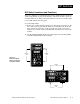
DIP Switches
O
N
↑
123
O
N
↑
123
O
N
↑
123
O
N
↑
123
O
N
↑
123
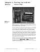
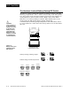
J, K, T, N, C, E, Pt2, D
Thermocouple Input
R, S, B
Thermocouple Input
RTD Input
0-5V, 1-5V or 0-10V Input
0-20mA or 4-20mA Input
Universal Signal Input Type DIP Switches
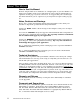
Remove the chassis from the case. Looking at the back of the control, the
input #1 (In1) switch is located at the base of the unit. Set the DIP switch-
es to match the appropriate sensor input types will automatically match
the DIP switch settings.
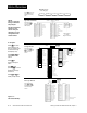
If you have model number
98_ C- 1 _ _ _-_ _ _ _
, there is no In1 DIP
switch.
Figure 1.6a -
Input DIP Switch
Locations.
Figure 1.6b -
Input DIP Switch
Settings.
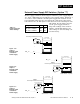
Single Input Unit
98_ C - 2_ _ _ - _ _ _ _