
User Manual


8 8LS User’s Guide
Introduction
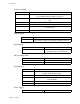
Control Capability
Digital Outputs
Digital Inputs
Pulse Counting Input
Serial Interface
Power Supply
Number of loops 8, dual output
Control outputs Cycle Time Proportioning, Distributed Zero Crossing, On/Off or Ana-
log; all independently selectable for each loop
Control action Reverse [heat] or Direct [cool], independently selectable for each
loop
Digital PID outputs Nominal 5 Vdc at 20 mA to drive optically-isolated solid-state relays
Cycle time Programmable for each loop, 1-255 seconds
Analog PID outputs Selectable 0 to 5 Vdc at 20 mA maximum or 4 to 20 mAdc 500 ohm
maximum load
Output resolution 12 bits
Number 31
Configuration 1 Global Alarm (terminals)
30 for alarms or events (1-4 terminals, 5-30 RTB connector)
Number 12
Configuration 12 for Ramp/Soak triggers
(1-8 RTB connector, 9-12 terminals)
Number Selectable 1 per unit
Type Open collector, 5 Vdc max.
Frequency 1 to 20 Khz
Type RS-232 or RS-485 4 wire, jumper select
Isolation RS-232: optical
RS-485: To RS-485 Specification
Baud Rate 2400 or 9600, menu selectable
Protocol Form of ANSI X3.28-1976, compatible with Allen Bradley
PLC, full Duplex
Error check BCC or CRC, menu selectable
No. of controllers Each communications line: 32 with RS-485, 1 with RS-232
Power input 85 to 132 Vac, .1A typical, 47 to 440 Hz