
User Manual


Installation
8LS User’s Guide 13
External Wiring
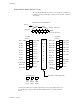
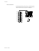
During wiring, it is recommended that the 8LS electronics be removed
or that temporary covers be put over the housing slots to ensure pieces
of wire do not enter the housing and lodge in the electronics. Always
ensure that the housing is clean when the electronics is plugged in.
A successful installation of an 8LS control system depends on selecting
the proper equipment and using correct installation techniques with
appropriate material. One area of concern is the wiring type and
placement of the wiring.
The wiring is selected according to the function of the wire, the
installation requirements, and the possible mechanical electrical
problems that may occur.
The function of the wire is divided into two basic categories:
Inputs
and
Outputs
. The process control requirements will dictate the
type
of
inputs and the outputs along with the mechanical electrical requirements
of the individual installation.
The term AC power is applied to the 120 VAC control supply. High
power is applied to 240 VAC or higher, primarily used for control loads.
General Wiring Requirements
1. Use stranded wire. Solid wire is recommended for fixed service
and tends to make intermittent connections when moving the field
wiring around for maintenance.
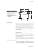
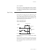
3.20’’
3.20’’
3.78’’
0.29’’0.91’’
0.29’’
3.78’’
Top
7/16 dia
Insert
g
rommet
125 dia
4 places
Remote Panel Mountin
g
Dimensions
Notes:
1. Dashed line indicates panel outline.
2. Drill holes as indicated.
3. Install
g
rommet and feed wire
through grommet.
4. Attach panel usin
g
4 #4 screws
(
from behind
)
.