
User Manual


Installation
8LS User’s Guide 29
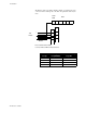
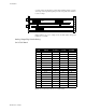
Digital Outputs On The Screw Terminal Blocks
NOTE
Alarms and events outputs are sinking +5vdc to
ground when the output is ON. They should be
connected to the minus (-) side of SSRs.
Connections are made as follows:
See Terminal Block and Connector Layout.
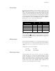
Primary Analog Outputs
The 8LS provides either 4 to 20mA with 500 ohms maximum load or 0-
5vdc at 5mA maximum. Selection is made on internal dip switches.
The control outputs are shipped as voltage outputs, and can be
converted from voltage to current by changing the dip switch settings on
the control output card. If you are using the output as a digital mode,
such as TPV, you should leave the output in voltage mode. These
switches are accessible from the top of the electronics assembly after it
has been removed from the housing.
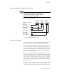
There are two dip switch packages on the Output Card, each with 8
switches. Each channel requires two switches. The dip switch package
near the rear panel controls the odd numbered outputs, while the dip
switch package near the front panel controls the the even channels.
When the unit is viewed from the top, with the rear panels to the left, the
channels are in ascending order from left to right [See silk screen on the
printed circuit board].
For each channel, a switch pair will have the switches set in
complementary states. If the first switch of the pair is down and the
second is up, the output is in voltage mode. If the first is up and the
+
_
++
__
Alarm
SSR 1
Event
SSR 2
Control
SSR 3
Pin
#
16
18
21
4
1
Screw Terminal
Block 2
Di
g
ital Out 1
(Alarm ON/OFF)
Di
g
ital Out 2
(Event On/Off)
+5Vdc Suppl
y
PID Ctl Out 1+
(TP or On/Off)
Lo
g
ic Ground