
Manual


WATLOW DIN-A-MITE Style C User's Manual
3
Additional Specifications: Phase Angle; Phase Angle Current Limit; & Single Cycle VTB
Operation
• Burst firing (zero-cross) control, single-cycle variable
time base, Type S single-phase and 3-phase. Unit is
not on for more than one full cycle under 50% power
and not off for more than one full cycle above 50%
power.
• Phase angle control, single-phase only
Input Command Signal
• 0 to 20mA, 4 to 20mA, 12 to 20mA, Î (dc), 0 to 5VÎ, 1
to 5VÎ, and 0 to 10VÎ
• Input impedance 250ž for 4 to 20mA, 5kž for linear
voltage input
Output Voltage
• 100 to 120VÅ (ac), 200 to 208VÅ, 230 to 240VÅ,
277VÅ, 400VÅ, 480VÅ, 600VÅ, -15%/+10%, 50 or
60 Hz independent +/-5% (Input Control Signal Type
L, P and S)
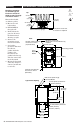
Phase Angle Accuracy
• Output on time is directly proportional to the command
signal. Output on time is accurate to within 5% of the
command signal input at 25 degrees C ambient. See
chart below for command signal input to output power
transfer function. Temperature stability at ambient
temperature is less than 0.25%/degrees C.
Single Cycle VTB Accuracy
• Output power is directly proportional to the command
signal. Output power is accurate to within 5% of the
command signal input at 25 degrees C ambient.
Temperature stability is less than 0.25%/degrees C
ambient temperature change.
Soft Start
(Phase Angle Input Control Signal Type P and L)
Typically:
• 5 seconds soft start on power up
• Soft start on thermostat overtemperature
• Soft start on 1/2 cycle drop out detection
• 1 second soft switching on set point change
Options
• Manual Control Kit (1kž potentiometer) 08-5362
• Alarm option is not available on phase angle type P or
type L.
Resolution
• Better than 0.1% of input span with respect to output
change.
Control Mode, Zero-Cross
• Input Control Signal Type C: VÎ (dc) input contactor.
To increase service life, the cycle time should be less
than 3 seconds.
• Input Control Signal Type K: VÅ (ac) input contactor.
To increase service life, the cycle time should be less
than 3 seconds.
• Input Control Signal Type F: 4 to 20mAÎ (dc)
proportional variable time base control.
Input Command Signal
• AC contactor
24VÅ ±10%, 120VÅ +10%/-25%, 240VÅ (ac)
+10%/-25% @ 25mA maximum per controlled leg
• Do not use the DIN-A-MITE Vac-input models with a
temperature controller that includes an RC snubber
circuit across its output. Remove the RC snubber
circuit before placing the DIN-A-MITE into service.
• DC Contactor
4.5 to 32VÎ (dc): maximum current @ 4.5VÎ
(dc) is 6mA per leg. Add 2mA per LED used to the
total current.
• Loop powered linear current
4 to 20mAÎ (dc): loop-powered. Input Type
F0 option only. (Requires current source with 6.2VÎ
(dc) available. No more than three inputs connected
in series.)
Linearity (Input Control Signal Type F)
• Full on point 19.5 to 19.9mAÎ (dc), maximum voltage
of 6.2V peak.
• ±5% input to output power accuracy, 0% to 100% of
span (4.3 to 19.7mA or 12.3 to 19.7mA).
• Temperature stability is less than 0.15%/°C change.
Additional Specifications for Contactors and Proportional Controls
0
.0
1
0
.
0
20
.
0
3
0
.0
4
0
.
0
5
0
.0
6
0
.0
7
0
.0
8
0
.
0
9
0
.
0
1
0
0
.
0
0
1
0
2
0
3
0
4
0
5
0
6
0
7
0
8
0
9
0
100
Command
Si
gnal Inpu
t (%P)
Output (%P)
Phase Angle Command Signal Input to Output Power