
Owner manual

Watlow EZ-ZONE
®
PM Integrated Controller • 127 • Chapter 9 Features
Sensor Selection
You need to configure the controller to match the input device, which is normally a thermocouple, RTD or
process transmitter.
Select the sensor type with Sensor Type [`Sen] (Setup Page, Analog Input Menu).
Sensor Backup
Sensor backup maintains closed-loop control after an input failure by switching control to input 2. The sensor
backup feature is only available in an EZ-ZONE PM Integrated Limit or Remote Set Point controller. Turn
sensor backup on or off with Sensor Backup Enable [`S;bA] (Setup Page, Analog Input 1).
Note:
When Sensor Backup is enabled the Process Value function will automatically set itself to Sensor Backup.
Set Point Low Limit and High Limit
The controller constrains the set point to a value between a set point low limit and a set point high limit.
Set the set point limits with Low Set Point [`L;SP] and High Set Point [`h;SP] (Setup Page, Loop Menu).
There are two sets of set point low and high limits: one for a closed-loop set point, another for an open-loop
set point.
Scale High and Scale Low
When an analog input is selected as process voltage or process current input, you must choose the value of volt-
age or current to be the low and high ends. For example, when using a 4 to 20 mA input, the scale low value
would be 4.00 mA and the scale high value would be 20.00 mA. Commonly used scale ranges are: 0 to 20 mA, 4
to 20 mA, 0 to 5V, 1 to 5V and 0 to 10V.
You can create a scale range representing other units for special applications. You can reverse scales from
high values to low values for analog input signals that have a reversed action. For example, if 50 psi causes a 4
mA signal and 10 psi causes a 20 mA signal.
Scale low and high low values do not have to match the bounds of the measurement range. These along with
range low and high provide for process scaling and can include values not measureable by the controller. Re-
gardless of scaling values, the measured value will be constrained by the electrical measurements of the hard-
ware.
Select the low and high values with Scale Low [`S;Lo] and Scale High [`S;hi]. Select the displayed range
with Range Low [`r;Lo] and Range High [`r;hi] (Setup Page, Analog Input Menu).
Range High and Range Low
With a process input, you must choose a value to represent the low and high ends of the current or volt-
age range. Choosing these values allows the controller’s display to be scaled into the actual working units of
measurement. For example, the analog input from a humidity transmitter could represent 0 to 100 percent
relative humidity as a process signal of 4 to 20 mA. Low scale would be set to 0 to represent 4 mA and high
scale set to 100 to represent 20 mA. The indication on the display would then represent percent humidity and
range from 0 to 100 percent with an input of 4 to 20 mA.
Select the low and high values with Range Low [`r;Lo] and Range High [`r;hi] (Setup Page, Analog In-
put Menu).
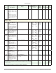
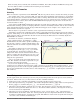
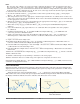
Set Point Range (must be between Range High and Range Low)
Low Limit of selected functional range
High Limit of selected functional range
Gas Pressure
Range Low and Range High
Range High Range (between High Limit of Sensor and Range Low)
Range Low Range (between Low Limit of Sensor and Range High)
Set Point Low
Set Point High