
Owner manual

Watlow EZ-ZONE
®
PM Integrated Controller • 128 • Chapter 9 Features
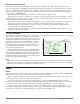
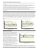
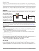
Receiving a Remote Set Point
The remote set point feature allows the controller to use a thermocouple, RTD, 1 k potentiometer or pro-
cess signal at input 2 to establish the set point, which allows its set point to be manipulated by an external
source. A common application would use one ramping controller with a set-point retransmit output to ramp
multiple controllers using the remote set point. Or you could use an analog output from a PLC to send set
point values to an EZ-ZONE PM.
The controller must have two process inputs to use the remote set point feature.
You may select between local and remote set points at the front panel, with an event input, from a remote
computer using the communications feature or from an external switch using an event input. Make sure all
input and output impedances are compatible.
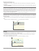
1. Switch to the remote set point with Remote Enable [`r;En] (Operations Page, Loop Menu). Select whether
the remote set point controls an open- or closed-loop set point with Remote Set Point Type [`r;ty].
2. Assign the function of switching to a remote set point to a digital input with Digital Input Function
[``Fn] (Setup Page, Digital Input Menu).
3. Assign the function of switching to a remote set point to the EZ Key with Digital Input Function [``Fn]
(Setup Page, Function Key Menu).
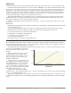
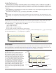
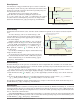
Ten Point Linearization
The linearization function allows a user to re-linearize a value read from an analog input. There are 10 data
points used to compensate for differences between the
sensor value read (input point) and the desired value
(output point). Multiple data points enable compensation
for non-linear differences between the sensor readings
and target process values over the thermal or process
system operating range. Sensor reading differences can
be caused by sensor placement, tolerances, an inaccu-
rate sensor or lead resistance.
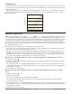
The user specifies the unit of measurement and then
each data point by entering an input point value and a
corresponding output point value. Each data point must
be incrementally higher than the previous point. The
linerization function will interpolate data points linear-
ly in between specified data points.
Note:
Output Point 1 will be the minimum value that can be displayed, and Output Point 10 will be the maximum
value that can be displayed. Consider setting Output Point 1 to the minimum operating range, and Output
Point 10 to the maximum operating range; for that sensor type.
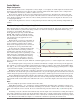
Outputs
Duplex
Certain systems require that a single process output control both heating and cooling outputs. An EZ-ZONE
®
PM controller with a process output can function as two separate outputs.
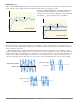
With a 4 to 20mA output the heating output will operate from 12 to 20mA (0 to +100 percent) and the cool-
ing output will operate from 12 to 4mA (0 to -100 percent).
In some cases this type of output is required by the device that the EZ-ZONE PM controls, such as a
three-way valve that opens one way with a 12 to 20mA signal and opens the other way with a 4 to 12mA sig-
nal. This feature reduces the overall system cost by using a single output to act as two outputs.
Outputs 1 and 3 can be ordered as process outputs. Select duplex [dUPL] as the Output Function [``Fn]
(Setup Page, Output Menu). Set the output to volts [uoLt] or milliamps [`MA] with Output Type [`o;ty].
Set the range of the process output with Scale Low [`S;Lo] and Scale High [`S;hi].
2
3
4
5
6
7
8
9
Reading from Sensor
without Linearization
(Actual Value)
Input Point 1
Output Point 1
Input Point 10
Output Point 10
Oset Zone
Reading from Sensor
with Linearization
(Displayed Value)
No Offset
Temperature
Time