
Owner manual

Watlow EZ-ZONE
®
PM Integrated Controller • 135 • Chapter 9 Features
Variable Time Base (cont.)
Variable time base should be used with solid-state power controllers, such as a solid-state relay (SSR) or
silicon controlled rectifier (SCR) power controller. Do not use a variable time base output for controlling elec-
tromechanical relays, mercury displacement relays, inductive loads or heaters with unusual resistance char-
acteristics.
The combination of variable time base output and a solid-state relay can inexpensively approach the effect
of analog, phase-angle fired control.
Select the AC Line Frequency [AC;LF] (Setup Page, Global Menu), 50 or 60 Hz.
Note:
When output 1 is a universal process output, output 2 cannot use variable time base, fixed time base only.
When output 3 is configured as a universal process, output 4 cannot use variable time base, fixed time base
only.
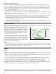
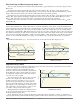
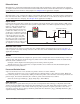
Single Set Point Ramping
Ramping protects materials and systems that cannot tolerate rapid temperature changes. The value of the
ramp rate is the maximum degrees per minute or hour that the system temperature can change.
Select Ramp Action [``rP] (Setup Page, Loop Menu):
[`oFF] ramping not active.
[`Str] ramp at startup.
[StPt] ramp at a set point change.
[both] ramp at startup or when the set point changes.
Select whether the rate is in degrees per minute or degrees per hour with Ramp Scale [`r;SC]. Set the ramp-
ing rate with Ramp Rate [`r;rt] (Setup Page, Loop Menu).
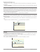
Cascade Control
The PM (PM4/8/9) can be configured for Cascade control with enhanced firmware. Cascade is used to opti-
mize the performance of thermal systems with long lag times. It utilizes a control strategy in which one con-
trol loop provides the set point for another loop. See Chapter 10 for application examples.
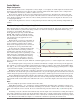
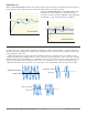
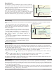
Compressor Control
The PM control can be configured for Com-
pressor control with enhanced firmware.
The compressor control can save wear on a
compressor and prevent it from locking up
from short cycling. A bypass valve operated
by a control output regulates how the pro-
cess is cooled, while another output switches
the compressor on and off. The compres-
sor will not turn on until the output power
exceeds the Power On Level % for a time
longer than the specified On Time. The com-
pressor will not turn off until the output
power is equal to or less than the Power Off
Level % for a time longer than the specified
Off Time.
Set Point
Time
Temperature
Heating System without Ramping
Temperature reaches Set Point quickly
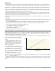
Set Point
Time
Temperature
Temperature ramps to Set Point at a set rate
degrees
per minute
Heating System with Ramping
0% Compressor
On Power
Off
On
100%
2%
0%
-100%
Compressor On Delay = 45 Seconds
Compressor Off Delay = 20 Seconds
2% Compressor
Off Power
Time In Seconds
% Power
Heat
Cool
Compressor