
Owner manual
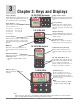

Watlow EZ-ZONE
®
PM Integrated Controller • 40 • Chapter 2 Install and Wire
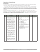
Warning: Óç
Use National Electric (NEC) or other
country-specific standard wiring and
safety practices when wiring and
connecting this controller to a power
source and to electrical sensors or
peripheral devices. Failure to do so
may result in damage to equipment
and property, and/or injury or loss
of life.
Note:
Maximum wire size termination and
torque rating:
• 0.0507 to 3.30 mm
2
(30 to 12
AWG) single-wire termination or
two 1.31 mm
2
(16 AWG)
• 0.8 Nm (7.0 lb.-in.) torque
Note:
Adjacent terminals may be labeled
differently, depending on the model
number.
Note:
To prevent damage to the control-
ler, do not connect wires to unused
terminals.
Note:
Maintain electrical isolation between
analog input 1, digital input-outputs,
switched dc/open collector outputs
and process outputs to prevent
ground loops.
Note:
The control output common termi-
nal and the digital common terminal
are referenced to different voltages
and must remain isolated.
Note:
This Equipment is suitable for use in
CLASS I, DIVISION 2, Groups A, B,
C and D or Non-Hazardous locations
only. Temperature Code T4A
Warning:
ç
Explosion Hazard - Dry contact clo-
sure Digital Inputs shall not be used
in Class I Division 2 Hazardous Loca-
tions unless switch used is approved
for this application.
Warning:
ç
Explosion Hazard – Substitution of
component may impair suitability
for
CLASS I, DIVISION 2.
Warning:
ç
Explosion Hazard - Do not discon-
nect while the circuit is live or
unless the area is known to be free
of ignitable concentrations of flam-
mable substances.
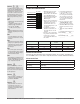
- A
+ B
com
98
99
CC
CA
CB
B5
D6
D5
power
- A
+ B
common
power
- A
+ B
common
power
power
power
power
EZ-ZONE PM
EZ-ZONE ST
ST_ _ - (B or F) _ M _ -_ _ _ _
PLC
98
99
CC
CA
CB
B5
D6
D5
Power
Supply
fuse
EZ-ZONE RM
98
99
S
l
o
t
C
power
CZ
CB
CX
CY
CA
CC
- A
+ B
common
- A
+ B
com
- A
+ B
common
power
- A
+ B
common
power
power
power
EZ-ZONE PM
EZ-ZONE ST
ST_ _ - (B or F) _ M _ -_ _ _ _
98
99
CF
CD
CE
B5
D6
D5
Power
Supply
fuse
EZ-ZONE RM
98
99
S
l
o
t
C
power
CZ
CE
CX
CY
CD
CF
- A
+ B
common
98
99
CF
CD
CE
B5
D6
D5
98
99
CF
CD
CE
RUI/Gateway
EZKB-_ A _ _- _ _ _ _
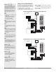
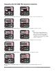
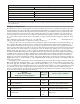
Do not route network wires with pow-
er wires. Connect network wires in
daisy-chain fashion when connecting
multiple devices in a network.
A termination resistor may be re-
quired.Placea120Ωresistoracross
T+/R+ and T-/R- of the last controller
on a network.
Only one protocol per port is avail-
able at a time: either Modbus RTU or
Standard Bus.
Wiring a Serial EIA-485 Network
A network using Watlow's Standard Bus and an RUI/Gateway.
A network with all devices configured using Modbus RTU.