
Owner manual

Watlow EZ-ZONE
®
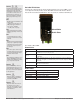
PM Integrated Controller • 41 • Chapter 2 Install and Wire
Warning: Óç
Use National Electric (NEC) or other
country-specific standard wiring and
safety practices when wiring and
connecting this controller to a power
source and to electrical sensors or
peripheral devices. Failure to do so
may result in damage to equipment
and property, and/or injury or loss
of life.
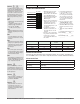
Note:
Maximum wire size termination and
torque rating:
• 0.0507 to 3.30 mm
2
(30 to 12
AWG) single-wire termination or
two 1.31 mm
2
(16 AWG)
• 0.8 Nm (7.0 lb.-in.) torque
Note:
Adjacent terminals may be labeled
differently, depending on the model
number.
Note:
To prevent damage to the control-
ler, do not connect wires to unused
terminals.
Note:
Maintain electrical isolation between
analog input 1, digital input-outputs,
switched dc/open collector outputs
and process outputs to prevent
ground loops.
Note:
The control output common termi-
nal and the digital common terminal
are referenced to different voltages
and must remain isolated.
Note:
This Equipment is suitable for use in
CLASS I, DIVISION 2, Groups A, B,
C and D or Non-Hazardous locations
only. Temperature Code T4A
Warning:
ç
Explosion Hazard - Dry contact clo-
sure Digital Inputs shall not be used
in Class I Division 2 Hazardous Loca-
tions unless switch used is approved
for this application.
Warning:
ç
Explosion Hazard – Substitution of
component may impair suitability
for
CLASS I, DIVISION 2.
Warning:
ç
Explosion Hazard - Do not discon-
nect while the circuit is live or
unless the area is known to be free
of ignitable concentrations of flam-
mable substances.
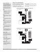
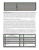
Connecting a Computer to PM Controls Using B&B 485 to USB Converter
Address 2
Address 1
Data Format
38,400 baud
8 data bits
no parity
1 start bit
1 stop bit
PC Software Protocol - Standard Bus
EZ-ZONE Congurator software
0847-0326-0000
USB
Port
Use twisted pair wires such as Cat 5 cabling. Do not route with power carrying
conductors. Daisy chain wire up to 16 EZ-ZONE devices.
Slot A
Slot B
Slot C
Slot A
Slot B
Slot C
Note:
Do not leave a USB to EIA-485 converter connected to Standard Bus with-
out power (i.e., disconnecting the USB end from the computer while leaving
the converter connected on Standard Bus). Disturbance on the Standard
Bus may occur.
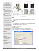
Note:
When connecting the USB converter to the PC it is suggested that the La-
tency Timer be changed from the default of 16 msec to 1 msec. Failure to
make this change may cause communication loss between the PC running
ZE-ZONE Configurator software and the control.
To modify Latency Timer settings follow the steps below:
1. Navigate to Device Manager.
2. Double click on Ports.
3. Right click on the USB serial port in use and select Properties.
4. Click the tab labeled Port settings and then click the Advance button.