PPC-2000 User’s Guide WATLOW 1241 Bundy Boulevard Winona, Minnesota USA 55987 Phone: +1 (507) 454-5300, Fax: +1 (507) 452-4507 Part No. 0600-3000-2000 Rev 2.3d http://www.watlow.
PPC-2000 Adaptive Control Addendum Scope This document describes the additional features and functionality found in the PPC-2010-xxB with adaptive control. Refer to the PPC-2000 User’s Guide regarding all other functionality which is the same as the standard version.
Adaptive Mode When Control Type is set to Adaptive, this parameter can be used to pause tuning or to reset the adaptive algorithm and have it relearn the system. This parameter has no effect on control if the Control Type for the loop is set to an option other than Adaptive. Values: Adapt (0), Reset (1) and Hold (2) Default: Reset (1) Modbus Address (Channels 1 to 32): 49001 to 49032 Parameter Number: 21 LogicPro Driver: Database LogicPro Address (Channels 1 to 32): 21.1 to 21.32 Table 1.
This parameter has no effect on control if the Control Type for the loop is set to an option other than Adaptive. Values: Automatic (0) and 1 (1) to 600 seconds (600) Default: Automatic (0) Modbus Address (Channels 1 to 32): 49051 to 49082 Parameter Number: 28 LogicPro Driver: Database LogicPro Address (Channels 1 to 32): 28.1 to 28.32 Tuning Gain This parameter indicates the amount of delay in seconds in the load. This characteristic of the load or plant has a significant impact on adaptive control.
a. In the PV Source field, choose the input that you want to monitor or use as feedback for closed-loop control. b. In the Heat Output Dest and/or Cool Output Dest fields, choose the outputs that you want to use for closed-loop control. c. Choose a Heat/Cool Output Type for each output. d. Set the Heat/Cool Cycle Time for any outputs with Heat/ Cool Output Type set to Time Prop. 4. On the Digital I/O spreadsheet: a. Set the Direction for each I/O point to be used for control to Output. 5.
PPC-2000 User's Guide Addendum Overview This document contains additional specifications for the PPC-2000 system. Environmental Specifications Table 1 here contains specifications in addition to those found in tables 7.4, 7.15, 7.23, 7.31, 7.39, 7.46, 7.52, 7.57, 7.62, 7.67 in the PPC-2000 User's Guide. TABLE 1.
Copyright © 1998-2002 Watlow Anafaze Information in this manual is subject to change without notice. No part of this publication may be reproduced, stored in a retrieval system, or transmitted in any form without written permission from Watlow Anafaze. Warranty Watlow Anafaze, Incorporated warrants that the products furnished under this Agreement will be free from defects in material and workmanship for a period of three years from the date of shipment.
Table of Contents Table of Contents iii List of Figures ix List of Tables xv Overview 1 Manual Contents 1 Getting Started 2 Safety symbols 2 Contacting Watlow Anafaze 2 Initial Inspection 2 Product Features 3 System Components 3 PPC-2000 Modules 6 PPC-2000 Terminal Boards 8 Additional Components 9 Safety 9 External Safety Devices 10 External Switch Disconnect 11 Battery Safety 11 Product Markings and Symbols 11 Hardware Installation 13 Power Supply Requirements 13 Mounting the Power Supply 15 Hardware C
Table of Contents PPC-2000 User’s Guide Mounting Terminal Boards 28 DIN Rail Mounting 31 DIN Rail Removal 32 Panel Mounting 33 System Wiring 34 Wiring Recommendations 35 Noise Suppression 35 Avoiding Ground Loops 37 Connecting I/O to the PPC-2010 37 Connecting the TB50 to the PPC-2010 Module 37 TB50 Connections 38 Connecting Digital Inputs 40 Connecting Counter or Frequency Inputs 41 Connecting Digital Outputs 41 SDAC Connections 43 Connecting Analog Inputs to the PPC-2021 — 2025 45 Connecting the AITB
PPC-2000 User’s Guide Table of Contents Operating with AnaWin3 89 Type Definitions 89 Closed-Loop Control 89 Feedback 90 Control Algorithm 90 Control Output Signal Forms 90 Heat and Cool Outputs 90 Prerequisites 93 Background 93 Using AnaWin3 to Tune 94 Alarms 95 Failed Sensor Alarms 95 Global Alarm 95 Process Alarms 95 Alarm Delay 96 Setting up Process and Deviation Alarms 97 Setting Input Signal Lo and Input Signal Hi 99 Setting Engineering Units 99 Setting PV Lo and PV Hi 99 Setting Decimal Places 100
Table of Contents PPC-2000 User’s Guide Troubleshooting 141 General Description 141 PPC-2010 Processor 141 Processor Module LEDs 147 PPC-2040 Digital I/O 151 PPC-207x Digital In 153 Troubleshooting and Corrective Actions 154 Digital Inputs and Outputs 154 Process Variable 154 Communications 155 Resetting Closed-Loop Control Parameters 156 Disabling Control 157 LogicPro and Modbus Reference 159 Overview 159 Text Conventions in the Database Sections 159 The PPC-2000 Database 160 Data Table Organization 16
PPC-2000 User’s Guide Table of Contents Tuning and Control 219 Introduction 219 Control Algorithms 220 On/Off Control 220 Output Control Forms 224 Output Filter 225 Proportional Band (PB) Settings 226 Integral Settings 226 Derivative Settings 227 General PID Constants by Application 228 Proportional Band Only (P) 228 Proportional with Integral (PI) 228 PI with Derivative (PID) 228 Specifications 229 System Specifications 229 Safety and Agency Approvals 229 Physical Specifications 230 Power Specification
Table of Contents viii PPC-2000 User’s Guide Watlow Anafaze Doc.# 30002-00 Rev 2.
List of Figures Overview 1 Figure 1.1—System Diagram 4 Figure 1.2—Sample PPC-2000 System 6 Hardware Installation 13 Figure 2.1—PPC-IPS-2 DIN Mounting Dimensions 15 Figure 2.2—PPC-IPS-2 Panel Mounting Dimensions 16 Figure 2.3—Sample Addresses 17 Figure 2.4—PPC-2010 Jumpers 19 Figure 2.5—PPC-2030 Jumpers and Switches 20 Figure 2.6—PPC-2040 Jumper Settings 21 Figure 2.7—PPC-205x Jumpers 23 Figure 2.8—Assembled Modules Top View 24 Figure 2.9—Assembled Modules Bottom View 25 Figure 2.
List of Figures PPC User’s Guide Figure 2.35—Connecting Linear Voltage Signals to Differential Inputs 1 and 2 52 Figure 2.36—Connecting Linear Voltage Signals to Single-ended Inputs 1 and 2 53 Figure 2.37—Connecting Current Inputs to a Differential Input Module: Input 1, 2, and 3 Shown 53 Figure 2.38—Connecting Current Inputs to a Single-ended Analog Input Module: Input 1 and 2 Shown 54 Figure 2.39—PPC-2030 Connections (Bottom View) 55 Figure 2.40—PPC-EITB-1 56 Figure 2.
PPC User’s Guide List of Figures Operating with AnaWin3 89 Figure 3.1—Sample Screen Text 89 Figure 3.2—Process Variable Alarms 96 Figure 3.3—Linear Input Example 98 Figure 3.4—Linear Scaling of the Analog Input for Retransmit on the Heat or Cool Output 102 Figure 3.5—Sample Application Using Process Variable Retransmit 104 Figure 3.6—How the Secondary Channel’s Set Point is Determined When the Primary Channel Has Heat and Cool Outputs 105 Figure 3.
List of Figures PPC User’s Guide LogicPro and Modbus Reference 159 Figure 5.1—Sample Text 160 Figure 5.2—Output Scaling Curves 185 Tuning and Control 219 Figure 6.1—On/Off Control 220 Figure 6.2—Proportional Control 221 Figure 6.3—Proportional and Integral Control 222 Figure 6.4—Proportional, Integral and Derivative Control 223 Figure 6.5—Example Time Proportioning and Distributed Zero Crossing Waveforms 224 Specifications 229 Figure 7.1—System Footprint 230 Figure 7.2—PPC-2010 Front View 231 Figure 7.
List of Tables Overview 1 Table 1.1—PPC-2000 System Modules 5 Table 1.2—PPC-2000 Terminal Boards and Peripheral Modules Table 1.3— Analog Terminal Board Keys 5 5 Hardware Installation 13 Table 2.2—Power Supply Current Requirements at 24Vdc 14 Table 2.3—Power Supply Screw Mounting 16 Table 2.4—System Modules and Addressing 18 Table 2.5—PPC-2010 Processor Module Jumpers 18 Table 2.6—PPC-2030 Analog Output Jumpers 21 Table 2.7—PPC-2040 Counter Input Jumpers 21 Table 2.
List of Tables PPC User’s Guide Operating with AnaWin3 89 Table 3.1—Control Types PID1 and PID2 91 Table 3.2—Alarm Types 95 Table 3.3—Range and Sensitivity of theCustom Linear Input Types 99 Table 3.4—PV Range permitted for various Decimal Places Settings 100 Table 3.5—Scaling Parameters for 0-10Vdc Linear Input Example 101 Table 3.6—Scaling Parameters for 4-20mA Linear Input Example 101 Table 3.7—Scaling Parameters for 0-1Vdc Linear Input Example 102 Table 3.
PPC User’s Guide List of Tables Table 5.38—Digital I/O Parameters 200 Table 5.39—State and Logic 201 Table 5.40—Direction 201 Table 5.41—Logic 201 Table 5.44—Soft Bool and Soft Int Parameters 205 Table 5.45—Soft Bool Values 205 Table 5.46—Soft Bool and Soft Int Registers 206 Table 5.47—Rotary Switch Configuration 207 Table 5.48—Communications Parameters 208 Table 5.49—Database Offsets for Baud Rate 208 Table 5.50—Baud Rate 208 Table 5.51—System HW Parameters 209 Table 5.
List of Tables PPC User’s Guide Table 7.24—Physical Specifications 241 Table 7.25—Connections 242 Table 7.26—Power Specifications 242 Table 7.27—Input Specifications 242 Table 7.29—Safety and Agency Approvals 243 Table 7.30—Model Number 244 Table 7.31—Environmental Specifications 244 Table 7.32—Physical Specifications 245 Table 7.33—Connections 245 Table 7.34—Power Specifications 245 Table 7.35—Counter/Frequency Specifications 245 Table 7.37—Digital Output Specifications 246 Table 7.
PPC User’s Guide List of Tables Table 7.78—Environmental Specifications 265 Table 7.79—Physical Specifications 266 Table 7.80—Safety and Agency Approvals 266 Table 7.81—Inputs 267 Table 7.82—Power Requirements 267 Table 7.83—Analog Output Specifications 267 Appendix A: Modbus Protocol 269 Table A.1—Example Message Frame 271 Table A.2—Function Codes 276 Table A.3—Sample Packet for Host Query 280 Table A.4—Sample Packet for Slave Response 280 Table A.5—Sample Packet for Host Query 281 Table A.
List of Tables xviii PPC User’s Guide Watlow Anafaze Doc.# 30002-00 Rev 2.
1 Overview Manual Contents This manual describes how to install, set up, and operate a PPC-2000 controller. Each chapter covers a different aspect of your control system and may apply to different users. The following describes each chapter’s purpose. Doc.# 30002-00 Rev 2.3 • Chapter 1: Overview. Provides component list and summary of features for the PPC-2000. • Chapter 2: Hardware Installation. Provides detailed instructions on installing the PPC-2000 system and its peripherals.
Chapter 1: Overview PPC-2000 User’s Guide Getting Started The following sections provide information regarding product features, system components, safety requirements, and preparation for operation. Safety symbols These symbols are used throughout this manual: ∫ WARNING! Indicates a potentially hazardous situation which, if not avoided, could result in death or serious injury.
PPC-2000 User’s Guide Chapter 1: Overview Product Features The PPC-2000 (PPC) offers high performance closed-loop (PID) control and the ability to manipulate process control algorithms and sequential logic in a very user friendly way. It is a modular programmable process control system that utilizes plug-in modules to meet different system requirements. The controller can be configured for as many as 48 channels of PID control and supports up to 288 programmable digital I/O points.
Chapter 1: Overview PPC-2000 User’s Guide The following hardware and software interfaces are provided: Hardware • Serial ports for interfacing host computers and thirdparty operator displays • Analog input and output terminal block connections • Digital input and output terminal block connections Software / Firmware PC for AnaWin3 HMI Software and/or LogicPro • Remote third-party operator interface panel software using Modbus protocol (option) • AnaWin3 Configurator edition: Windows configurati
PPC-2000 User’s Guide Chapter 1: Overview Table 1.
Chapter 1: Overview PPC-2000 User’s Guide Figure 1.2 Sample PPC-2000 System PPC-2000 Modules The following sections describe the purpose and features of each type of module available with the PPC-2000 system. PPC-2010 Processor Module The PPC-2010 processor module houses the system microprocessor, memory and controller programs.
PPC-2000 User’s Guide Chapter 1: Overview The PPC-2010 has 48 built-in digital I/O points. 24 points are outputs only. 22 of these outputs are user configurable for PID control, alarms or logic outputs. The other 2 outputs are dedicated to system status and global alarm. The remaining 24 I/O points are individually configurable as either inputs or outputs.
Chapter 1: Overview PPC-2000 User’s Guide PPC-2030 Encoder In Analog Out Module The PPC-2030 is used in applications including monitoring and controlling belt speeds, motor speeds, positioning, etc. Four isolated analog outputs are jumper configurable for current or voltage. These outputs may be used to provide software selectable analog output signals to field devices. Four counter inputs are used for interfacing to motor encoder signals.
PPC-2000 User’s Guide Chapter 1: Overview PPC-EITB-1 Encoder Input Terminal Board The EITB is a DIN rail or panel mountable terminal block card which provides means to interface with motor encoders. Two pulse inputs (single ended or differential, single or quadrature phased) may be connected to the screw terminals. A 5Vdc power source interconnect is provided to supply encoders. PPC-TB50-SCSI 50-Pin Terminal Board The TB50 connects to the Processor or Digital I/O module through the SCSI connector.
Chapter 1: Overview PPC-2000 User’s Guide ∫ WARNING! Power, input or output circuits with hazardous voltage levels should not have any live accessible parts. ∫ WARNING! In any application, failures can occur. These failures can result in full control output (100% power), or the occurrence of other output failures which can cause damage to the controller, or to the equipment or process connected to the controller.
PPC-2000 User’s Guide Chapter 1: Overview External Switch Disconnect ∫ WARNING! Provide a labeled switch or circuit breaker connected to the PPC-2000 power wiring as the means of disconnection for servicing. Failure to do so could result in damage to equipment and/or property, and/ or injury or death to personnel. The disconnect should be located so that operators and technicians can access it quickly and easily.
Chapter 1: Overview 12 PPC-2000 User’s Guide Watlow Anafaze Doc.# 30002-00 Rev 2.
2 Hardware Installation This section describes how to install your PPC system hardware. It provides detailed instructions for each component and peripheral item. Read this chapter before installing your PPC-2000 system. Power Supply Requirements Watlow Anafaze provides the PPC-IPS2 power supply for the PPC-2000 system. This unit supplies sufficient current for a processor and various combinations of I/O modules. For specification information on the power supply, refer to Chapter 7, Specifications.
Chapter 2: Hardware Installation PPC-2000 User’s Guide Table 2.1 Power Supply Current Requirements at 12Vdc Module Number of modules PPC-2010 1 Current x 250mA = PPC-202x (max. 4) x 390mA = PPC-2030 (max. 4) x 900mA = PPC-2040 (max. 6) x 300mA = x 800mA = x 500mA = PPC-206x (max. 6) x 250mA = PPC-207x (max. 4) x 100mA = total current required = PPC-2050 PPC-2051 (max. 4) Total Number of Modules (max. 10) Table 2.
PPC-2000 User’s Guide Chapter 2: Hardware Installation ∫ WARNING! The PPC is designed to operate on 12-28Vdc. Connection to a power source other than this will cause damage to the PPC. To avoid electrical shock, correctly connect the power supply’s earth ground. Mounting the Power Supply Mount the hardware in an area free of moisture or corrosive chemicals. Mount the power supply vertically with adequate vent space.
Chapter 2: Hardware Installation PPC-2000 User’s Guide 1.97 in. 0.24 in. 1.32 in. All Vented 115 7.5 in. 0.10 in. 7.84 in. 0.93 in. 0 79 i Figure 2.2 PPC-IPS-2 Panel Mounting Dimensions To DIN rail mount the PPC-IPS-2: 1. Locate a space with sufficient room for the power supply and connecting wires. Refer to Figure 2.1 on page 15. 2. Install a section of DIN rail. 3. Hook the top of the DIN rail latch over the DIN rail such that the spring is under the lip of the rail. 4.
PPC-2000 User’s Guide Chapter 2: Hardware Installation Hardware Configuration In order for multiple PPC modules to function together, each needs to be addressed correctly. Some of the PPC modules may require jumper or switch settings to work with field input and output devices. The following sections describe the configuration options and procedures. Module Addresses Each module in a PPC assembly must have a unique address. The PPC-2010 module is fixed as module address 0 in the firmware.
Chapter 2: Hardware Installation PPC-2000 User’s Guide Table 2.4 System Modules and Addressing Module Max.
PPC-2000 User’s Guide Chapter 2: Hardware Installation Flash memory Chip (firmware) Battery Notch JU1 Termination Jumper B A Notch B A JU1 Port 1 JU2 B A Not Terminated Position Figure 2.4 PPC-2010 Jumpers PPC-2030 Dip Switch Settings Switch settings in the PPC-2030 determine whether encoder inputs accept single phase or quadrature encoder signals. Each of the four inputs is configured individually, therefore single phase and quadrature inputs may be mixed in a module.
Chapter 2: Hardware Installation PPC-2000 User’s Guide {Improve illustration. More like 2.6 and 2.7.} Counter Input Number 1 2 3 4 51 S1 .. .. .. .. .. .. .. .. .. .. .. .. .. .. .. .. ................ SV4 Single Phase Quadrature Analog Output Jumpers ... ... Figure 2.5 ... ... ... ... JU4 ... ... JU3 v i Current Position JU2 v i Voltage Position JU1 ... ... ... ...
PPC-2000 User’s Guide Chapter 2: Hardware Installation Table 2.6 PPC-2030 Analog Output Jumpers Analog Output Jumper # i (current) position* V (volt) position* 1 JU4 0-20mA 0-10Vdc 2 JU3 0-20mA 0-10Vdc 3 JU2 0-20mA 0-10Vdc 4 JU1 0-20mA 0-10Vdc * Listed values are maximum ranges. Other ranges within these limits may be selected in software. PPC-2040 Jumper Settings Each of the counter inputs on the PPC-2040 can be configured for single phase or quadrature input.
Chapter 2: Hardware Installation PPC-2000 User’s Guide PPC-205x Jumper Settings Each of the analog outputs on the PPC-205x modules may be configured either as a voltage output or a current output. A mixture of current and voltage outputs may be used on a particular module. The jumpers only determine if the output signal is current or voltage. The actual span of the signal is software selectable. See Heat/Cool Output Type in Channels section on page 119 for the various analog output signal settings.
PPC-2000 User’s Guide Chapter 2: Hardware Installation Analog Output Jumpers JU1 I V JU2 I V V I JU3 JU4 I V JU5 I V JU6 I V JU7 I V I Current Position V Voltage Position JU8 I V ... ... I V ... ... JU8 (2050: Output 8) JU7 (2050: Output 7, 2051: Output 4) JU6 (2050: Output 6) JU5 (2050: Output 5, 2051: Output 3) JU4 (2050: Output 4) JU3 (2050: Output 3, 2051: Output 2) JU2 (2050 Output 2) JU1 (Output 1) Figure 2.7 Doc.# 30002-00 Rev 2.
Chapter 2: Hardware Installation PPC-2000 User’s Guide Module Assembly Modules should be assembled prior to mounting. The processor module is always the first module (left side) on a PPC system. To connect other modules, use the following procedure. ç CAUTION! To avoid damaging your PPC system, never connect or disconnect modules that are powered. ç CAUTION! PPC modules contain sensitive electronic components. Be sure to observe ESD safety precautions such as wearing a ground strap. 1.
PPC-2000 User’s Guide Chapter 2: Hardware Installation 2. Align the 4 interconnect tabs and their related slots, as well as the module expansion bus connector. Front Module bottom latch (locked) Back Figure 2.9 Module bottom latch (unlocked) Assembled Modules Bottom View Slot Tab Module bottom latch (locked) Module bottom latch (unlocked) Figure 2.10 Modules Bottom/Side View Doc.# 30002-00 Rev 2.3 3.
Chapter 2: Hardware Installation PPC-2000 User’s Guide Module Disassembly To separate modules, reverse the procedure in Module Assembly on page 24. When separating modules, gently rock and pull the modules apart. ç CAUTION! To avoid damaging your PPC system, never connect or disconnect modules that are powered.
PPC-2000 User’s Guide Chapter 2: Hardware Installation DIN Rail Mounting 1. Each module in the assembly has a DIN rail latch. Pull all the latches to the open position. See Figure 2.11. DIN Rail Latch (closed) DIN Rail Latch (open) Figure 2.11 DIN Rail Latches 2. Place the module assembly on the upper lip of the DIN rail; push the lower side of the assembly over the lower lip of the DIN rail. See Figure 2.12. Upper lip of DIN Rail DIN Rail Latch (open) Push to lock Figure 2.
Chapter 2: Hardware Installation PPC-2000 User’s Guide Panel Mounting The PPC modules may be panel mounted using the mounting holes located on the end plates. The width of a system varies depending on the number of modules. Consult Figure 7.1 on page 230 to determine installed clearances. To panel mount the modules: 1. Locate a space with sufficient room for the appropriate number of modules and connecting wires. Refer to Figure 7.1 on page 230 for a system footprint and dimensions. 2.
PPC-2000 User’s Guide Chapter 2: Hardware Installation For more detailed specification information, refer to Chapter 7, Specifications. 3.6" (91 mm) 2.0" (51 mm) 5.1" 4.70" (128 (119mm) mm) 5.756" 5.10" L (146mm) mm) (130 2.6" (66 mm) 4.0" W (102 mm) Figure 2.13 AITB Dimensions / Clearances Doc.# 30002-00 Rev 2.
Chapter 2: Hardware Installation PPC-2000 User’s Guide 2.2 in. (56 mm) 3.4 in. (86 mm) 3.8 in. L (97 mm) 1.6 in. (41 mm) 2.0 in. W (51 mm) Figure 2.14 EITB Dimensions / Clearances 30 Watlow Anafaze Doc.# 30002-00 Rev 2.
PPC-2000 User’s Guide Chapter 2: Hardware Installation 3.6 in. (91 mm) 2.3 in. (58 mm) 3.4 in. (86 mm) 4.1in. L (104 mm) 2.6 in. (66 mm) 4.2 in.W (102 mm) Figure 2.15 TB50 Dimensions / Clearances DIN Rail Mounting All factory terminal boards snap onto a DIN rail. A TB50 is shown in the following figures for illustration purposes only. To install a terminal board on a DIN rail, place the hook side of the mounting mechanism over one of the DIN rail lips and snap the board over the other lip. Doc.
Chapter 2: Hardware Installation PPC-2000 User’s Guide Hook side Figure 2.16 TB50 Mounted on DIN Rail (Front) DIN Rail Removal Place a flat blade screw driver through the slot in the board and hook the blade into the snap latch. Pry the snap latch away from the DIN rail lip and repeat for the other side. See Figure 2.17. Removal catch for screwdriver DIN Rail snap latch Hook side Figure 2.17 TB50 Mounted on DIN Rail (Side) 32 Watlow Anafaze Doc.# 30002-00 Rev 2.
PPC-2000 User’s Guide Chapter 2: Hardware Installation Panel Mounting NOTE! When panel mounting terminal boards, remove the DIN rail brackets before mounting the boards. Standoff Figure 2.18 TB50 Panel Mounted Stand-offs are provided for all terminal boards. Doc.# 30002-00 Rev 2.3 1. Remove the DIN rail mounting brackets from terminal board. 2. Select a location with enough clearance for the board and its SCSI cable. Refer to Figure 2.15 on page 31 for installed clearances. 3.
Chapter 2: Hardware Installation PPC-2000 User’s Guide Mounting an SDAC Module Follow these steps to install the SDAC module: 1. Select a location for installation. The SDAC is designed for wall mounting. It should be installed as close to the controller as possible. 2. Mark and drill four holes for screw mounting. Use the diagrams below for the correct locations. 3. Install the unit with the four #4 screws. 3.60 in. (91 mm) Electrical connections 3.00 in. (76 mm) 4.68 in. (119 mm.
PPC-2000 User’s Guide Chapter 2: Hardware Installation ç CAUTION! Power, input or output circuits with hazardous voltage levels should not have any live accessible parts. Wiring Recommendations Keep the following guidelines in mind when selecting wires and cables: • Use stranded wire. (Solid wire can be used for fixed service; but it makes intermittent connections when you move it for maintenance.) • Use #20 AWG TC extension wire.
Chapter 2: Hardware Installation PPC-2000 User’s Guide electromechanical relays, alarm horns and motor starters. Such devices may generate electromagnetic interference (EMI or noise). If the controller is placed close to sources of EMI, it may not function correctly. Below are some tips on how to recognize and avoid problems with EMI. Symptoms of RFI/EMI If your controller displays the following symptoms, suspect EMI: • Measured values for analog inputs fluctuate or are incorrect.
PPC-2000 User’s Guide Chapter 2: Hardware Installation • You can use other voltage suppression devices, but they are not usually required. For instance, you can place a metal oxide varistor (MOV) rated at 130Vac for 120Vac control circuits across the load, which limits the peak AC voltage to about 180Vac. You can also place a transorb (back to back zener diodes) across the digital output, which limits the digital output voltage. The above steps will eliminate most EMI/RFI noise problems.
Chapter 2: Hardware Installation PPC-2000 User’s Guide TB50 pin 1 50-pin SCSI Connector PPC-2010 Bottom View Figure 2.20 PPC-2010 Connection to TB50 NOTE! If more than one module in the PPC system is connected to a terminal board using a 50-pin SCSI connector, label each end of each cable and each terminal board with the address of the module to which it should be connected. TB50 Connections Connect digital inputs and digital outputs for control signals, alarms, and digital field I/O to the TB50.
PPC-2000 User’s Guide Chapter 2: Hardware Installation Table 2.10 Module I/O Number Doc.# 30002-00 Rev 2.3 Processor Module I/O Connections TB-50 Terminal AnaWin3 Name (Dig I/O Spreadsheet)1 PPC1:Proc 0.0.1 Digital In/Out 1 Counter 1 Frequency 1 1 PPC1:Proc 0.1.1C2 PPC1: Proc 0.2.1 F Digital In/Out 2 2 PPC1: Proc 0.0.2 Digital In/Out 3 3 PPC1: Proc 0.0.3 Digital In/Out 4 4 PPC1: Proc 0.0.4 Digital In/Out 5 5 PPC1: Proc 0.0.5 Digital In/Out 6 6 PPC1: Proc 0.0.
Chapter 2: Hardware Installation PPC-2000 User’s Guide Module I/O Number TB-50 Terminal AnaWin3 Name (Dig I/O Spreadsheet)1 Digital Out 35 35 PPC1: Proc 0.0.35 Digital Out 36 36 PPC1: Proc 0.0.36 Digital Out 37 37 PPC1: Proc 0.0.37 Digital Out 38 38 PPC1: Proc 0.0.38 Digital Out 39 39 PPC1: Proc 0.0.39 Digital Out 40 40 PPC1: Proc 0.0.40 Digital Out 41 SDAC Out 41 41 PPC1: Proc 0.0.41 Digital Out 42 SDAC Out 42 42 PPC1: Proc 0.0.42 Digital Out 43 SDAC Out 43 43 PPC1: Proc 0.0.
PPC-2000 User’s Guide {Add examples with transistor inputs on digital and pulse inputs.} Chapter 2: Hardware Installation Digital Input Device TB50 Digital In Com Figure 2.21 Wiring Digital Inputs Connecting Counter or Frequency Inputs PPC-2010 module accepts a single-phase pulse signal from devices such as encoders. Counts and frequencies of the inputs may be scaled with user selectable parameters. See Setting up User Selectable Linear Inputs on page 98 for more information.
Chapter 2: Hardware Installation PPC-2000 User’s Guide + 12-24 - PS PPC 2010 TB50 +5 Digital Out SSR Figure 2.23 Powering Output with 5Vdc from PPC Supply + PS - PPC 2010 TB50 Digital Out SSR Figure 2.24 Powering Output with 12-24Vdc from PPC supply + PS for controller PS for Output - PPC 2010 TB50 Digital Out SSR Figure 2.25 Powering Output with Separate Power Supplies 42 Watlow Anafaze Doc.# 30002-00 Rev 2.
PPC-2000 User’s Guide Chapter 2: Hardware Installation Using the CPU Watchdog Signal The PPC system constantly monitors the functioning of its microprocessor. The CPU watchdog output is Low (on) when the microprocessor is operating; when it stops operating, the output goes High (off). This sink output is available on screw terminal #48 on the TB50 attached to the PPC-2010 Processor module. The figure below shows the recommended circuit for the CPU Watchdog signal output.
Chapter 2: Hardware Installation PPC-2000 User’s Guide Multiple SDAC Systems As many as 5 SDACs can be run from one PPC-2000. Be sure to provide sufficient current. Use stranded 18 to 22 gauge wire for most installations. Refer to Figure 2.27 for system setup. • Connect SDAC Pin 1 to the +5V terminal on the power supply. • Connect SDAC Pin 2 to the DC COM terminal on the power supply. • If a separate power supply is used, connect the common to the DC COM on the PPC-2000 power supply.
PPC-2000 User’s Guide Chapter 2: Hardware Installation Connecting Analog Inputs to the PPC-2021 — 2025 The Analog Input Terminal Board (AITB) connects to the analog input module through the SCSI connector (bottom center of the analog input module). The AITB accommodates wiring thermocouples, RTDs, and voltage/current linear inputs. AITB PPC-202X 50-pin SCSI Connector Figure 2.28 PPC-2021 — 2025 Connection to AITB Connecting the AITB to the PPC-202x Refer to Figure 2.28.
Chapter 2: Hardware Installation PPC-2000 User’s Guide Sensor Keys Sensor keys with built-in jumpers or resistors are used to customize the AITB for various sensor types. Insert the appropriate key in the socket provided on the AITB. See Table 2.11 for a description of the various keys. There are two rows of eight key sockets. Each socket location is labeled IN1 to IN16 which correlate with each Analog In or High Isolation Analog input address.
Chapter 2: Hardware Installation P1 PPC-2000 User’s Guide Indicates component side Color indicates key type Figure 2.30 An Input Key AITB Connections The AITB accommodates wiring thermocouples, RTDs, and voltage/current linear inputs for all analog input modules. Table 2.12 describes each analog module and Table 2.13 on page 48 correlates the AITB labels with the sensor wire connections for the various modules. When connecting sensor wires, tighten to 0.5 – 0.6 Nm, or 4.5 – 5.4 inch-pound. Table 2.
Chapter 2: Hardware Installation PPC-2000 User’s Guide Table 2.
PPC-2000 User’s Guide Chapter 2: Hardware Installation Table 2.14 Power Connections on AITB Voltage NOTE! AITB Terminals 10.00V Ref Ref (4 PL.) Analog Common Com (8 PL.) The Ref voltage is provided for special sensor types. Do not use this voltage without consulting Watlow Anafaze. Connecting Thermocouples NOTE! Connect thermocouple shields directly to a good frame or chassis ground. Connect thermocouple shields at one end only, either near the terminal board or the sensor end.
Chapter 2: Hardware Installation PPC-2000 User’s Guide A T/C is connected to a single-ended input by wiring the positive signal lead to the A or B terminal and the negative signal lead to the analog COM terminal. See Figure 2.32 and refer to Table 2.13 on page 48. ∫ WARNING! Thermocouples connected to single-ended inputs (PPC-2022) must be isolated (ungrounded) and should not be embedded within heater elements as some cartridge heaters are constructed. .
PPC-2000 User’s Guide Chapter 2: Hardware Installation AITB 1A (input 1+) 1B (input 1-) 2A (input 2+) 2B (input 2-) COM Figure 2.33 Wiring 2-Wire RTDs: Input 1 and 2 Shown Three-wire RTDs may only be used with differential analog input modules. The single wire side of a 3-wire RTD sensor A terminal, one of the double wire sides connects to the COM B terminal and the other connects to the COM connects to the A B terminal. Both A and B terminals must be of the same desired input, i.e., 1A and 1B.
Chapter 2: Hardware Installation PPC-2000 User’s Guide ç CAUTION! Do not connect the COM terminals on the AITB to earth ground. Connecting COM to earth ground limits the input protection to ±10Vac and could result in damage to the input circuit. Connecting Sensors with Linear Voltage Signals For sensors with single output connections, connect the negative input (B terminal) to the sensor common terminal.
PPC-2000 User’s Guide Chapter 2: Hardware Installation AITB + Transducer with linear voltage output 1A (input 1+) - + Transducer with linear voltage output 2A (input 2+) A COM Figure 2.36 Connecting Linear Voltage Signals to Single-ended Inputs 1 and 2 Connecting Sensors with Linear Current Signals Differential current transducers or sensors should be connected with the positive signal lead on the A terminal and the negative signal lead to the B terminal for the selected input. See Figure 2.37.
Chapter 2: Hardware Installation PPC-2000 User’s Guide {Redraw like other I/O diagrams.} + power 28V Max Power Supply + – Typical 2-wire current transmitter I + power 28 V Max Typical 3-wire current source transmitter – – 1A(Input 1+) Com I 2A(Input 2+) Com Figure 2.38 Connecting Current Inputs to a Single-ended Analog Input Module: Input 1 and 2 Shown 54 Watlow Anafaze Doc.# 30002-00 Rev 2.
PPC-2000 User’s Guide Chapter 2: Hardware Installation Connecting Encoders and Analog Outputs to the PPC-2030 The PPC-2030 accepts four encoder inputs and outputs four current or voltage signals. Encoder signals are connected to the module via two HD-15 cables. These cables may be used in conjunction with up to two EITBs or may be connected directly from the encoders to the module. Connect analog outputs via the analog output terminal block as shown in Figure 2.39.
Chapter 2: Hardware Installation PPC-2000 User’s Guide EITB Connections Table 2.15 and Table 2.16 indicate the encoder connections to the EITB connected to the Encoder In Analog Out module. Table 2.17 on page 57 lists the terminals that carry power. pin 1 J2 pin 12 Figure 2.40 PPC-EITB-1 Table 2.15 Module I/O Number Count 1 Frequency 1 Count 2 Frequency 2 Table 2.
PPC-2000 User’s Guide Chapter 2: Hardware Installation Table 2.17 Power Connections on EITB Voltage EITB Terminals +5Vdc 1, 7 COM 6, 12 Encoder Wiring The EITB accommodates four configurations of frequency/ counter inputs: • Single-ended/single phase • Single-ended/quadrature • Differential/single phase • Differential/quadrature Note that these are four unique inputs and each input has two phases. Both phases are used only in quadrature mode nominally.
Chapter 2: Hardware Installation PPC-2000 User’s Guide 1+ Q1 2+ EITB 2 (input 1 phase 1+) 4 (input 1 phase 2+) COM 1+ 8 (input 2 phase 1+) 2+ 10 (input 2 phase 2+) Q2 COM 12 (COM) Figure 2.42 EITB Single-ended Quadrature Connections: Input 1 and 2 Shown EITB S1 + 2 (input 1 phase 1+) - 3 (input 1 phase 1-) 12 (COM) + S2 - 8 (input 2 phase 1+) 9 (input 2 phase 1-) 12 (COM) Figure 2.43 EITB Differential Single Phase Connections: Input 1 and 2 Shown 58 Watlow Anafaze Doc.
PPC-2000 User’s Guide Chapter 2: Hardware Installation EITB 2 (input 1 phase 1+) 1+ 3 (input 1 phase 1-) 1Q1 2+ 4 (input 1 phase 2+) 2- 5 (input 1 phase 2-) 12 (COM) 1+ 8 (input 2 phase 1+) 1- 9 (input 2 phase 1-) 2+ 10 (input 2 phase 2+) 2- 11 (input 2 phase 2-) Q2 12 (COM) Figure 2.44 EITB Differential Quadrature Connections: Input 1 and 2 Shown Encoder Connections without the EITB Encoders may be connected directly to the PPC-2030 module. Table 2.17 and Table 2.
Chapter 2: Hardware Installation PPC-2000 User’s Guide Table 2.19 HD-15 Power Connections Voltage Pin Number +5Vdc 12, 15 COM 13, 14 Analog Output Connections The connector pinouts are shown in Table 2.20. Use 16-28 AWG wire. When making connections, tighten to 0.5 to 0.6 Nm, or 4.5 to 5.4 inch-pound. J2 44+ 33+ J1 22+ 11+ Outputs 3 & 4 Outputs 1 & 2 DIN Rail Latch Figure 2.45 PPC-2030 Analog Out Terminal Block Table 2.
PPC-2000 User’s Guide Chapter 2: Hardware Installation P PC-2030 1+ + + 4-20mAdc - I 1- Load - 2+ + + 0-10Vdc - Load 2- - Figure 2.46 Analog Output Connections on a PPC-2030: Outputs 1 and 2 Shown Connecting I/O to the PPC-2040 A TB50 connects to a PPC-2040 Digital I/O module through the 50 pin SCSI connector. Refer to Figure 2.47 on page 62. The terminal block interfaces to field wiring of the digital I/O (sensors, actuators, relays, SSRs, etc.).
Chapter 2: Hardware Installation PPC-2000 User’s Guide TB50 pin 1 50-pin SCSI Connector PPC-2040 Bottom View Figure 2.47 PPC-2040 Connection to TB50 NOTE! To avoid confusing the SCSI cables during servicing, label each end of each cable and each terminal board with the address of the module to which it should be connected. TB50 Connections Connect digital inputs and digital outputs for control signals, alarms, and digital field I/O to the TB50.
PPC-2000 User’s Guide Chapter 2: Hardware Installation Table 2.
Chapter 2: Hardware Installation PPC-2000 User’s Guide Connecting Digital Inputs The PPC-2040 module can accept digital inputs. When the resistance of an input device is 27 kOhm or greater, the input is considered off by the PPC-2000. When the resistance is 1 kOhm or less, the input is considered on. To install a switch as a digital input, connect one lead to the DC Common input return on the TB50. Connect the other lead to the desired digital input on the TB50. Refer to Table 2.
PPC-2000 User’s Guide Chapter 2: Hardware Installation TB50 1 (input 1 phase 1+) 1+ Q1 2 (input 1 phase 2+) 2+ COM 3 (input 2 phase 1+) 1+ 4 (input 2 phase 2+) 2+ Q2 COM 37 (COM) Figure 2.50 Quadrature Connections: Inputs 1 and 2 Shown. Connecting Digital Outputs The digital outputs sink current from a load connected to the controller’s power supply, or another power supply referenced to the PPC-2000 power common. Do not exceed +24 volts.
Chapter 2: Hardware Installation PPC-2000 User’s Guide + PS PPC - Digital Out TB50 SSR Figure 2.52 Powering Output with 12-24Vdc from PPC supply + PS for controller PS for Output PPC Digital Out TB50 +5 to 24Vdc SSR Figure 2.53 Powering Output with Separate Power Supplies 66 Watlow Anafaze Doc.# 30002-00 Rev 2.
PPC-2000 User’s Guide Chapter 2: Hardware Installation Connecting Analog Outputs to the PPC-205x Connect wires directly to the terminals on the bottom of the PPC-205x modules. The PPC-2050 can source up to eight analog signals and the PPC-2051 up to four. Table 2.22 lists the terminal connections for the PPC-2050 module. 16-pin Terminal Block for Analog Outputs PPC-2050 PPC-2051 Figure 2.54 PPC-205x Connections (Bottom View) Table 2.
Chapter 2: Hardware Installation NOTE! PPC-2000 User’s Guide On the PPC-2050, each consecutive pair of analog outputs—1-2, 3-4, 5-6 and 7-8—shares an internal power supply. In current mode the power supply + is shared, and in voltage mode the common is shared. If an external power supply is tied into the internal power supply though the B pin, the signal to each output may be distorted. It may be necessary to use a separate external power supply for each analog output within the pair.
PPC-2000 User’s Guide Chapter 2: Hardware Installation PPC-2050 1A + v + - Load - 1B 2A + v + - Load - 2B com Figure 2.56 Analog Output Connections on a PPC-2050 Configured for Voltage: Outputs 1 and 2 shown PPC-2051 1A Sink - i I 1B Load + Source 2A + v + Load 2B - Figure 2.57 Analog Output Connections on a PPC-2051 Configured for Current and Voltage: Outputs 1 and 2 shown NOTE! Doc.# 30002-00 Rev 2.
Chapter 2: Hardware Installation PPC-2000 User’s Guide Connecting to the Relay Outputs on the PPC-206x The PPC-2061 and PPC-2062 provide connections located on the bottom panel for eight electromechanical relay outputs and three counter inputs. Relay output field wiring is terminated at a sixteen position removable terminal block. 16-pin terminal block for relay outputs Common Terminals PPC-2062 PPC-2061 Figure 2.58 PPC-206x Connections (bottom view) 70 Watlow Anafaze Doc.# 30002-00 Rev 2.
PPC-2000 User’s Guide Chapter 2: Hardware Installation Wiring PPC-2061 Relay Outputs The PPC-2061 has 16 normally open relay outputs. Outputs 1 to 8 share one common, and outputs 9-16 share the second common. Either AC or DC may be switched. See Figure 2.59 for an example of how to connect to the relay outputs. Table 2.23 on page 72 lists the connections to the PPC-2060 and PPC-2061 modules.
Chapter 2: Hardware Installation PPC-2000 User’s Guide PPC-2062 1A Load L2 (AC) Relay 1 AC or DC Source 1B 2A L1 (AC) Load Relay 2 L2 (AC) AC or DC Source 2B L1 (AC) Figure 2.60 Relay Output Connections on a PPC-2062: Outputs 1 and 2 Shown Table 2.
PPC-2000 User’s Guide Chapter 2: Hardware Installation Using Snubbers for Relay Outputs Relay contacts can arc and/or generate EMI. Over time, arcing will shorten the life of relay contacts and EMI can disrupt system functions. Use snubbers—a resistor and capacitor in series— to protect against EMI and lengthen relay life. The capacitor should be non-polarized and may be metallized polyester film or metallized polypropylene and the voltage rating must be 600Vdc/250Vac.
Chapter 2: Hardware Installation PPC-2000 User’s Guide Connecting Digital Inputs to the PPC-207x Connect wires directly to the terminals on the bottom of the PPC-207x modules. Up to 16 inputs are accommodated. Depending on the module type, DC and AC inputs are accommodated. Input Connections Common Connections PPC-2070 PPC-2072 PPC-2071 PPC-2073 Figure 2.
PPC-2000 User’s Guide Chapter 2: Hardware Installation Input Device (PPC-2073 only) ----- PPC-2071/ PPC-2073 1 Input Device 2 ----- + DC DC Source Source + --- --Input Device Å C1 Input Device (PPC-2073 only) ----- 9 Input Device ----+ DC DC Source Source + 10 Å C2 --- --- Figure 2.64 Input Connections to a PPC-2071 or PPC-2073: Inputs 1,2, 9 and 10 Shown PPC-2072/ PPC-2073 C/C1 V+ + DC Source - Sensor’s Output 1 Sensor Circuit VCurrent Sinking Field Device Figure 2.
Chapter 2: Hardware Installation PPC-2000 User’s Guide PPC-2072/ PPC-2073 C/C1 V– DC Source + Sensor’s Output 1 Sensor Circuit V+ Current Sourcing Field Device Figure 2.66 Connecting a Current Sourcing Field Device to a PPC-2072 or PPC-2073: Input 1 Shown Table 2.
PPC-2000 User’s Guide Chapter 2: Hardware Installation Connecting Power PPC-IPS-2 Power Supply The PPC-IPS-2 accepts two ranges of voltages. Connections are made at screw terminals. Table 2.25 PPC-IPS-2 Voltage Input Switch Settings IPS-2 Switch Setting Input Voltage Range 115V 88-132Vac 230V 176-264Vac Input Frequency 47-440Hz ç CAUTION! The PPC-IPS-2 accepts two ranges of voltage. Be sure to set the switch to the appropriate range before applying power.
Chapter 2: Hardware Installation PPC-2000 User’s Guide V1 +5 Vdc V1 +5 Vdc V2 +24 Vdc +24 Vdc DC Com Figure 2.67 PPC-IPS-2 Power Connections Connecting Communication Ports Communications ports 1 and 2 on the PPC-2010 Processor module may be used to communicate with an operator interface terminal, a computer running AnaWin3, LogicPro, or thirdparty software, or any device capable of acting as a host using the Modbus RTU protocol. PPC controllers always act as servers or slaves.
PPC-2000 User’s Guide Chapter 2: Hardware Installation Communication Cables Watlow Anafaze supplies flat, oval cables with modular plug and DB-9 connectors for RS-232. RS-485 cables have RJ12 connectors and bare-wire ends. These cables may be used for short runs between a PPC and a host device or between a PPC and a terminal strip or other wiring interface. When using other cables or connecting over longer distances, select cables and connectors that meet the standards described in this section.
Chapter 2: Hardware Installation PPC-2000 User’s Guide Table 2.
PPC-2000 User’s Guide Chapter 2: Hardware Installation Connecting RS-232 Communications RS-232 may be used for communications between one PPC and a host device over cables of up to 50 feet in length. RS-232 does not support more than two devices on a network. See Figure 2.69. RS-232 may be used to connect a computer, through a 232/485 converter, to an RS-485 communications network with up to 32 PPC controllers. See Figure 2.70. RS-232 4-pin RJ-type Serial Port DB-9 or DB-25 RS-232 Cable Figure 2.
Chapter 2: Hardware Installation PPC-2000 User’s Guide The host computer uses one twisted pair to send messages to any PPC on the network. All the PPCs receive all the messages. The one PPC addressed by a particular message uses the other twisted pair to respond. This twisted pair is shared by the transmitters of all the PPCs on the network. Only one PPC transmits at a time.
PPC-2000 User’s Guide Chapter 2: Hardware Installation Table 2.30 485 Terminal Block Pin Assignment 485 Terminal Block Pin Number PPC-2010 485 Port Pin Number Function 1 1 Common 2 2 RB + 3 3 TB + 4 4 TA - 5 5 RA - 6 6 Not used S Not used Not used Cable Recommendations Watlow Anafaze recommends Belden #9843 or its equivalent. This cable includes three, 24 AWG, shielded, twisted pairs. It should carry signals of up to 19.
Chapter 2: Hardware Installation Converter or Host PPC-2000 User’s Guide Color (RJ Pin) PPC 1 Yellow (5) Black (2) Green (4) RXB/RDB/RX+ RA- Black (2) RB+ RB+ Green (4) RXA/RDA/RX- TARed (3) TB+ White/Blue (1) Signal Common DC Common PPC N Yellow (5) RA- TXA/TDA/TXTXB/TDB/TX+ Color (RJ Pin) Red (3) White/Blue (1) Not Used External Termination Resistor TATB+ Signal Common Not Used Figure 2.
PPC-2000 User’s Guide Chapter 2: Hardware Installation Signal Common Each controller and the converter should be connected to the signal common to insure they can properly interpret the signals on the network. Pin #1 in the RJ12 connectors connects the signal commons of all the PPCs to each other. At the converter connect the signal common to the common of the converter’s DC power supply.
Chapter 2: Hardware Installation PPC-2000 User’s Guide Modbus Network Address For multiple PPC installations, each PPC-2010 must have a unique network address. As many as 32 PPC systems may communicate on a network. Both port 1 and 2 have the same network address. Network addresses 1 through 4 can be set using the rotary switch on the processor module.
PPC-2000 User’s Guide Chapter 2: Hardware Installation Setting Programmable Modbus Addresses Modbus addresses one through four may be set using the rotary switch on the face of the PPC-2010 Processor Module. See Modbus Network Address on page 86 for information on setting the rotary switch. The following procedure describes how to set other addresses: ∫ WARNING! Power is shut off to the PPC during the following procedure. Power cycling will interfere with process control.
Chapter 2: Hardware Installation 88 PPC-2000 User’s Guide Watlow Anafaze Doc.# 30002-00 Rev 2.
3 Operating with AnaWin3 This section describes how to use your PPC system with AnaWin3, the Watlow Anafaze HMI software. For hardware installation and configuration information, refer to Chapter 2, Hardware Installation. For AnaWin3 installation and user information, refer to the AnaWin3 User’s Guide. Type Definitions In the following sections, a special font or typeface is used to indicate text seen on the AnaWin3 screens: LP Enable Set this field to enable or disable the low process alarm.
Chapter 3: Operating with AnaWin 3 PPC-2000 User’s Guide Feedback Electrical signals from a sensor used to determine a control output is feedback. The Input parameters determine how the electrical signal is interpreted. Many standard sensor types are pre-programmed into the PPC-2000 and can be selected during setup. The controller interprets or scales the electronic signals for these sensor types in engineering units (°F or °C). Other sensor types may require user-supplied scaling information.
PPC-2000 User’s Guide Chapter 3: Operating with AnaWin 3 The PPC-2000 provides two methods for coordinating a heat and a cool output driven by a single channel. The Control Type parameter offers two choices PID1 and PID2. Table 3.1 describes these two algorithms. Table 3.1 Doc.# 30002-00 Rev 2.3 Control Types PID1 and PID2 PID1 Only the heat output or the cool output is on at any instant in time. The spread parameter provides a minimum switching hysteresis between the two outputs.
Chapter 3: Operating with AnaWin 3 PPC-2000 User’s Guide Setting up Control Channels Closed-loop control channels can be set up in various ways in the PPC-2000. The following procedure identifies the basic steps: 1. 2. 3. See Inputs on page 127 for descriptions of the input parameters. On the Inputs spreadsheet: a. Choose the appropriate Input Type for the sensor connected to each analog input you have wired. b. Choose Units for each analog input. c.
PPC-2000 User’s Guide Chapter 3: Operating with AnaWin 3 Autotuning Autotuning is a process by which a controller determines the correct PID parameters for optimum control. Prerequisites Before autotuning the controller, it must be installed with control and sensor circuitry and the thermal load in place. It must be safe to operate the thermal system, and the approximate desired operating temperature (set point) must be known.
Chapter 3: Operating with AnaWin 3 PPC-2000 User’s Guide Tuning Method The steps to autotune a channel are: NOTE! 1. In manual control set the set point to the value you will use for the autotune. 2. Note the value of the input filter. 3. Set the input filter to 0 scans. 4. Set the control mode to tune. 5. Wait for the channel to autotune. 6. Restore the input filter to its original value. 7. Note the PID parameters for future reference.
PPC-2000 User’s Guide Chapter 3: Operating with AnaWin 3 Alarms The controller has three different kinds of alarms: failed sensor alarms, the global alarm, and process alarms. For information on each of these alarms, refer to the following sections. Failed Sensor Alarms Failed sensor alarms indicate T/C breaks and failed RTDs due to open leads.
Chapter 3: Operating with AnaWin 3 PPC-2000 User’s Guide High and low process and deviation alarms activate when the process variable goes outside the limits set by the user. The alarm remains active until both the process variable comes within the limit and the deadband, and the alarm is acknowledged. Any digital output not used as a control output can be assigned to a process alarm. The output activates when the alarm is active.
PPC-2000 User’s Guide Chapter 3: Operating with AnaWin 3 Setting up Process and Deviation Alarms To enable alarms on the process variable for a channel follow these steps. See Alarms on page 123 for descriptions of the alarm parameters. On the Alarms spreadsheet: Doc.# 30002-00 Rev 2.3 1. Set the Alarm Deadband. 2. Set the Alarm Delay. 3. For each alarm you wish to activate: a. Set the alarm limits in the corresponding fields: LP Limit, LD Offset, HD Offset, HP Limit. b.
Chapter 3: Operating with AnaWin 3 PPC-2000 User’s Guide Setting up User Selectable Linear Inputs The Input Type and linear scaling fields (Input Signal Lo, Input Signal Hi, PV Lo and PV Hi) appear on the Inputs spreadsheet. Linear input types are used with sensors whose signals are straight line (linear) functions of the quantity being measured.
PPC-2000 User’s Guide Chapter 3: Operating with AnaWin 3 Choosing a Linear Input Type To set up a linear input first choose an Input Type. There are seven user selectable linear input types: three input types for voltage signals, one for current, two for frequencies, and one for counts. Pick an Input Type with the appropriate signal type (voltage, current, frequency or counts). Also choose an Input Type with the appropriate range and sensitivity for the sensor.
Chapter 3: Operating with AnaWin 3 PPC-2000 User’s Guide the sensor signal is at the level set in the Input Signal Hi field. Both parameters are entered in units for the input. Setting Decimal Places Set the Decimal Places parameter to determine how many decimal places are entered and displayed in the Process Variable, Set Point and alarm limits (LP Limit, LD Offset, HD Offset, HP Limit) for channels with the corresponding input selected as the PV Source.
PPC-2000 User’s Guide Chapter 3: Operating with AnaWin 3 Linear 0-10Vdc Input Example For a sensor that measures pressures from 0.0 to 15.0 psia and outputs a 0-10Vdc signal, set the following parameters: Table 3.5 Scaling Parameters for 0-10Vdc Linear Input Example Parameter Input Type Setting Units Linear -1 to 10 (v) Units psia Input Signal Lo 0.000 V Input Signal Hi 10.000 V PV Lo 0.0 psia PV Hi 15.
Chapter 3: Operating with AnaWin 3 PPC-2000 User’s Guide Linear 0-1Vdc Input Example For a sensor that measures light intensity between 0 and 500 Lumens and outputs a 0-1Vdc signal, set the following parameters: Table 3.7 Scaling Parameters for 0-1Vdc Linear Input Example Parameter Setting Input Type Units Linear -0.1 to 1 (v) Units Lumens Input Signal Lo 0.0 mV Input Signal Hi 1000.0 mV PV Lo 0 Lumens PV Hi 500.
PPC-2000 User’s Guide Chapter 3: Operating with AnaWin 3 A channel cannot be used for closed-loop control when it is configured as a retransmit channel. Setting up Process Variable Retransmit On the Channels spreadsheet for the channel that will output the retransmit signal: 1. Set the Control Type to PV Retransmit. 2. Set the PV Source to the same setting as the PV Source parameter of the channel to be retransmitted or any other analog input you want to retransmit. 3.
Chapter 3: Operating with AnaWin 3 PPC-2000 User’s Guide 4. Set the Cool Scale Hi to a percent of the range of the selected cool output type. This is the signal level that will be transmitted when the analog input selected as Set Point Source is at the value you entered for Max Set Point. 5. Set the Control Mode for the channel to Auto.
PPC-2000 User’s Guide Chapter 3: Operating with AnaWin 3 Cascade Control Cascade control is used with thermal systems with long lag times, which cannot be as accurately controlled with a single control loop. To accomplish this, the output of the primary channel is used to adjust the set point of the secondary channel. The secondary channel executes the actual control. In some applications, two zone cascade control systems are used.
PPC-2000 User’s Guide Set Point of the Secondary Channel (Engineering Units) Chapter 3: Operating with AnaWin 3 Max Set Point Min Set Point 0% 100% Primary Channel’s Heat Output (% of Full Scale) Figure 3.7 How the Secondary Channel’s Set Point is Determined When the Primary Channel Has Only a Heat Output Setting up Cascade Control To setup cascade control: 1. Set up the primary loop. See Cascade Control Example below. 2.
PPC-2000 User’s Guide Chapter 3: Operating with AnaWin 3 Tank Inner TC Channel 1 Input PPC Outer Channel 2 Heat Output Inner Outer TC Channel 2 Input Heater Power Control Figure 3.8 Sample Application Using Cascade Control outer TC is selected as the PV Source for For cascade control the inner the primary channel, and the inner outer TC is selected as the PV Source for the secondary channel. The secondary channel’s output is used to control the heater.
Chapter 3: Operating with AnaWin 3 PPC-2000 User’s Guide Table 3.10 Parameter Secondary Channel Parameter Settings Setting Description PV Source PPC1:AI 1.2 The inner outer TC is selected for the secondary channel. Set Point Source Channel 1 Out For cascade control, the primary channel’s output determines the secondary channel’s set point. Min Set Point 150°F When the primary channel’s output is 0% the secondary channel’s set point is 150°F.
Chapter 3: Operating with AnaWin 3 Set Point of the Secondary Channel (Engineering Units) PPC-2000 User’s Guide 190°F 170°F 150°F 0% 50% 100% Primary Channel’s Heat Output (% of Full Scale) 150°F 145°F 140°F Primary Channel’s Process Variable (°F) Figure 3.9 The Secondary Channel’s Set Point is Determined by the Primary Channel’s Process Variable Ratio Control Using ratio control the process variable of one channel or any analog input can determine the set point of another channel.
PPC-2000 User’s Guide Set Point of the Ratio Channel (Engineering Units) Chapter 3: Operating with AnaWin 3 Max Set Point tio ter t+ Min Set Point PV P *S Ra s Ma fse SP Of SP Offset Sensor Range High Sensor Range Low Master Channel’s Process Variable (Engineering Units) Figure 3.10 Relationship between the Master Channel’s Process Variable and the Ratio Channel’s Set Point. Setting up Ratio Control To set up ratio control: 110 1.
PPC-2000 User’s Guide Chapter 3: Operating with AnaWin 3 Ratio Control Example A chemical process requires a formula of two parts water to one part Potassium Hydroxide (KOH) to produce diluted Potassium Hydroxide. The desired flow of water is 10 gallons per second (gps) and the KOH should flow at 5 gps. Separate feeder pipes for each chemical feed in to a common pipe. The flow rate of each feeder pipe is measured by flow transducers providing 05Vdc signals to analog inputs on a PPC.
Chapter 3: Operating with AnaWin 3 PPC-2000 User’s Guide Differential Control Differential control is a special case of ratio control. With differential control, as with ratio, the set point of one channel is determined by the process variable value of another channel. The set point of the differential channel is calculated by adding an offset (Set Point Offset) to the process variable value of the master channel. The Set Point Ratio parameter is set to 1.
PPC-2000 User’s Guide Chapter 3: Operating with AnaWin 3 Setting up Analog Inputs for Use with a Logic Program The closed-loop control program updates any analog input whether it is selected as the source for a channel or not. A logic program can read and use the scaled Input Value from the PPC’s datatable. Set up the input as you would for a closed-loop control channel. Select an Input Type, set the Units, and set scaling parameters if using a Linear Input type.
Chapter 3: Operating with AnaWin 3 PPC-2000 User’s Guide ç CAUTION! The logic program will begin executing immediately after clicking the Send button. Assure that the equipment is in a safe condition to run logic. To stop the logic program: 1. Select the View menu. 2. Select PPC Globals. 3. Double-click on the Stop Logic Program button. 4. Click the Send button to command the PPC to stop the logic program -orclick Cancel.
PPC-2000 User’s Guide Chapter 3: Operating with AnaWin 3 Controller Parameters View and set the parameters that determine how the PPC interprets inputs, performs closed-loop control, operates outputs, and monitors process variables for alarm conditions on AnaWin3’s Spreadsheet Overview screen. Select the buttons on the PPC tab to configure the seven spreadsheets (Channels, Alarms, Inputs, Dig I/O, Outputs, Soft INT, and Soft BOOL), each detailed below.
Chapter 3: Operating with AnaWin 3 PPC-2000 User’s Guide Set Point The set point is the desired value for the process variable. Use this field to enter a set point for the selected channel. If the set point entered is out of the defined range, the controller assigns the closest number within the range. Range: same as the range of the input type selected. See Table 3.14 on page 130.
PPC-2000 User’s Guide Chapter 3: Operating with AnaWin 3 PV Source Select the input used as the process variable for this channel. Choose one of the displayed analog inputs. Use the scroll bar in the pop-up window to view the available inputs. Range: Not Assigned and all the analog inputs on the Inputs spreadsheet. Set Point Source Select a setting to determine how the set point for the channel is set. Select User for normal closed-loop control applications.
Chapter 3: Operating with AnaWin 3 PPC-2000 User’s Guide Control Type Select the function of the channel. Refer to Table 3.12. Refer to Heat and Cool Outputs on page 90 for more on PID1 and PID2. Table 3.12 AnaWin3 Control Types Control Type Description PID1 Heat and Cool outputs used to control. Only one output may be on at a time. PID2 Heat and Cool outputs used to control. Both outputs can be on at the same time.
PPC-2000 User’s Guide Chapter 3: Operating with AnaWin 3 Heat/Cool Man Reset Enter a value to add to the PID output calculation. When the corresponding Integral is set to zero, the value substitutes for the integral sum portion of the feedback calculation. In this case, the output equals the heat/cool manual reset value when the process variable is at set point.
Chapter 3: Operating with AnaWin 3 PPC-2000 User’s Guide Table 3.13 Output Type AnaWin3 Output Types Description Function Time Prop digital, time proportioned Percent output converted to a percent duty cycle over the user-selected fixed time. DZC digital, distributed zero crossing (not available for mechanical relay outputs) Output on/off state calculated for every AC line cycle.
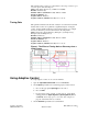
PPC-2000 User’s Guide Chapter 3: Operating with AnaWin 3 100 100 90 80 80 Actual Output Applied 60 (%) Linear 79 70 66 62 60 50 A 48 44 40 40 36 30 20 20 10 3 0 19 13 8 2 19 12 7 4 29 27 B Calculated Closed-Loop Control Action (%) 100 Figure 3.13 Output Scaling (Heat/Cool) Curves With Lag Curve A or Lag Curve B selected, a PID calculation results in a lower actual output level than the linear output requires.
Chapter 3: Operating with AnaWin 3 PPC-2000 User’s Guide Heat/Cool Limit Time Set a time limit for the Auto Heat/Cool Limit. If set to 0, the heat/ cool limit is in affect whenever the channel is in automatic control. Range: 0 to 32767 seconds Heat/Cool Scale Lo A control output may be linearly scaled by setting this parameter. Enter the percent of the output range of the selected Heat/Cool Output Type that should correspond to a calculated Heat/Cool Output% of 0%. Range: 0.0% to 100.
Heat/Cool Scale Lo Set this parameter in conjunction with Heat/Cool Scale Hi to scale the output or to change the control action. (See table 3.x.) Enter the value, as a percent of range, that the output should approach as the process variable approaches the set point from below for a heat output or from above for a cool output. See Figure 3.x. The default and typical value is 0%. For example, as a heater raises the temperature of a load towards set point, the output decreases toward 0%.
Figure 3.
PPC-2000 User’s Guide Chapter 3: Operating with AnaWin 3 Alarms Parameters on the Alarms spreadsheet enable and set the behavior of the process and deviation alarms for each channel. Figure 3.14 Alarms Spreadsheet Select the Alarms button to configure or monitor PPC alarm parameters. Channel names are located in the first column; each channel has a row of associated alarm parameters. For example, PPC1:Channel 3 indicates PPC #1 and channel #3.
Chapter 3: Operating with AnaWin 3 PPC-2000 User’s Guide HP Output Dest Choose a digital output to toggle when the high process alarm occurs. This may be any available hardware output or Soft Boolean register accessible by the logic program. The default for this parameter is Not Assigned. Outputs that are already assigned to control output destinations will be rejected. The same output may not be used for multiple alarm output destinations.
PPC-2000 User’s Guide Chapter 3: Operating with AnaWin 3 LD Offset Designate an offset value that determines the low deviation alarm limit relative to the current set point. The low deviation alarm occurs when the process variable is lower than the channel set point less this value. The alarm limit changes when the set point changes. The default low deviation alarm offset is 0. Range: same as the range of the input type selected. See Table 3.15 on page 130.
Chapter 3: Operating with AnaWin 3 PPC-2000 User’s Guide LP Enable Set this field to enable or disable the low process alarm. When it is Enabled, the low process alarm activates if the process variable (PV) dips below the LP Limit. The PV must rise above the LP Limit plus the alarm deadband to be reset (cleared). When this parameter is set to Disabled, the low process alarm does not occur. Range: Enable or Disable LP Output Dest Choose a digital output to toggle when the low process alarm occurs.
PPC-2000 User’s Guide Chapter 3: Operating with AnaWin 3 Inputs Parameters on the Inputs spreadsheet determine how measurements of signals from sensors attached to the analog input modules are read and scaled into engineering units for use by closed-loop control channels, monitor channels and logic programs. Figure 3.15 Inputs Spreadsheet PPC1:AI 1.3 module I/O number module address module type abbreviation controller number Figure 3.
Chapter 3: Operating with AnaWin 3 PPC-2000 User’s Guide The Processor module, Digital I/O, and Encoder In Analog Output modules accept pulse inputs. Both the count and frequency of each pulse signal are listed as inputs. Pulse input names identify the PPC, module, I/O type and module I/O number and indicate counter (C) or frequency (F). See example in Figure 3.17. PPC1:Proc 0.1.2 F Frequency/Counter module I/O number I/O type module address module type controller number Figure 3.
PPC-2000 User’s Guide Chapter 3: Operating with AnaWin 3 PPC1:Channel 1 Output channel number controller number Figure 3.19 Channel Output Names Table 2.15 on page 56 correlates module I/O numbers with screw terminals on the EITB. Input Value (PV) This field displays the scaled and filtered value measured by the sensor attached to the corresponding input. This field is read-only. Range: Depends on input type selected. See Table 3.15. Input Status This field displays information about the sensor.
Chapter 3: Operating with AnaWin 3 PPC-2000 User’s Guide Table 3.15 Input Types Input Type 130 Sensor Range Low Sensor Range High No Input N/A N/A Volts: -1 to 10V -1Vdc 10Vdc Volts: -0.5 to 5V -0.5Vdc 5Vdc Volts: -0.1 to 1V -0.1Vdc 1Vdc Volts: -50 to 500mV -50mVdc 500mVdc Volts: -10 to 100mV -10mVdc 100mVdc Volts: -5 to 50mV -5mVdc 50mVdc Linear -1 to 10 (V) -1.000Vdc 10.000Vdc Linear -0.1 to 1 (V) -100.0mVdc 1000.0mVdc Linear -10 to 100 (mV) -10.00mVdc 100.
PPC-2000 User’s Guide Chapter 3: Operating with AnaWin 3 NOTE! The counter and frequency inputs update four times per second (4Hz), except the Linear 0-300 (Hz) input type, which updates once every 25 seconds (.04Hz). The update rate of all other input types depends on the module. See Chapter 7, Specifications. Units For temperature sensors, choose the temperature scale for the input value. For custom linear and pulse type inputs, choose a three-character description of the input’s engineering units.
Chapter 3: Operating with AnaWin 3 PPC-2000 User’s Guide Input Signal Lo For linear inputs (see Setting up User Selectable Linear Inputs on page 98), enter the sensor signal level that corresponds to the low process value entered in PV Lo (see below). The input Signal Lo is entered in the units of the Input Type. Range: Depends on Input Type selected. See Table 3.15 on page 130.
PPC-2000 User’s Guide Chapter 3: Operating with AnaWin 3 Select the Dig I/O button to configure or monitor PPC Digital I/O parameters. I/O names are located in the first column. The I/O names identify each I/O point. Names for Processor (PPC-2010) and Digital I/O (PPC-204X) modules differ slightly from Digital Out (PPC-206X) and Digital In (PPC-207X) names. Processor and Digital I/O names include an I/O type designator because those modules support digital, count, and frequency types.
Chapter 3: Operating with AnaWin 3 PPC-2000 User’s Guide Table 3.17 Module Abbreviations Seen on the Digital I/O Spreadsheet Module Type Abbreviation PPC-2010 Processor Proc PPC-204x Digital I/O DIO PPC-206x Digital Out DO PPC-207x Digital In DI State This field indicates the state of the digital I/O in the system. I/O points configured as inputs are read-only. Range: 0 or 1 NOTE! The state must be interpreted in terms of the Logic setting in order to know if the I/O point is on or off.
PPC-2000 User’s Guide Chapter 3: Operating with AnaWin 3 Outputs The Outputs spreadsheet lists the output value for each of the analog outputs. Output behavior is set by the parameters of the channel with the output set as the output destination on the Channels spreadsheet. Figure 3.23 Outputs Spreadsheet Select the Outputs button to monitor the analog output values. Analog Output names are located in the first column.
Chapter 3: Operating with AnaWin 3 PPC-2000 User’s Guide Value This parameter displays the output value of the analog output as a number between 0 and 32767. These numbers correspond to the minimum and maximum output signal levels for the selected Output Type. The analog signal range is determined by the hardware, jumper configuration, and the setting of the Output Type on the Channels spreadsheet for the channel with the output selected as Heat/Cool Output Dest.
PPC-2000 User’s Guide Chapter 3: Operating with AnaWin 3 Soft Boolean The Soft Bool spreadsheet lists the values of each of the 1000 software Boolean registers set aside in the PPC database for exchanging data with the logic program. Figure 3.26 Soft BOOL Spreadsheet Select the Soft Bool button to monitor or edit the software Boolean values. Double click a field to change the setting. The left column in the spreadsheet lists the name of the register.
Chapter 3: Operating with AnaWin 3 PPC-2000 User’s Guide PPC Globals Select PPC Globals from the View menu to display the screen in Figure 3.27. Figure 3.27 PPC Globals Screen PPC Controller Select Select the pertinent controller to display its parameters on this screen. Ambient Temperatures The analog input modules measure the temperatures of each terminal block on up to four AITBs in tenths of degrees F. These give the cold junction compensation temperature for each half of the terminal block.
PPC-2000 User’s Guide Chapter 3: Operating with AnaWin 3 System Status Refer to Table 3.20 for a description of the system status parameters. Table 3.
Chapter 3: Operating with AnaWin 3 PPC-2000 User’s Guide Time and Date The PPC-2000’s clock calendar automatically updates the year, day of the week, month, date, hour, minute and second. Program Version The Program Version is an embedded program version label for the firmware program. This selection is read-only. View the program version by selecting About from the Help menu. 140 Watlow Anafaze Doc.# 30002-00 Rev 2.
4 Troubleshooting This chapter describes troubleshooting methods and fault indicators that may be useful if you experience difficulties with your PPC-2000 system. Appropriate remedial procedures are detailed below.
Chapter 4: Troubleshooting PPC-2000 User’s Guide Firmware Installation Procedures Changing the firmware on the processor module involves minor mechanical disassembly and reassembly of the controller. Appropriate precautions should be taken to prevent electrostatic discharge damage to the electronic components. Wear a grounding strap and place components on static-free grounded surfaces only. A small flathead screwdriver is needed.
PPC-2000 User’s Guide Chapter 4: Troubleshooting Back Module top latch (unlocked) Module top latch (locked) Front Figure 4.1 Assembled Modules Top View Front Module bottom latch (locked) Back Figure 4.2 Doc.# 30002-00 Rev 2.3 Module bottom latch (unlocked) Assembled Modules Bottom View 7. Gently rock and pull the modules apart. 8. Refer to Figure 4.3 on page 144 to locate the flash memory chip on the controller board.
Chapter 4: Troubleshooting PPC-2000 User’s Guide 9. Insert the new flash memory chip into the socket as shown in Figure 4.3, with the beveled edge and notched corner of the flash memory chip facing the bottom edge of the module. Be careful not to bend any legs while installing. 10. Reassemble the controller. 11. When the module is properly seated, close the two module latches by pushing the latches toward the front of the module. The two modules should be properly locked. 12.
PPC-2000 User’s Guide Chapter 4: Troubleshooting Battery Installation Procedures Changing the battery on the processor module involves minor mechanical disassembly and reassembly of the controller. Appropriate precautions should be taken to prevent electrostatic discharge damage to the electronic components. Wear a grounding strap and place components on static-free grounded surfaces only. A small flathead screwdriver is needed.
Chapter 4: Troubleshooting PPC-2000 User’s Guide Front Module bottom latch (locked) Module bottom latch (unlocked) Back Figure 4.5 PPC Assembled Modules Bottom View 6. Gently rock and pull the modules apart. 7. Refer to Figure 4.3 on page 144 to locate the battery on the controller board. Hold the controller board with the battery side facing down a few inches above a table or bench top. Pull up on the battery’s spring tab and allow the battery to slip out of its housing and to the table top.
PPC-2000 User’s Guide Chapter 4: Troubleshooting 15. Reset the controller and download the AnaWin3 Snapshot. Refer to Resetting Closed-Loop Control Parameters on page 156. 16. Reload logic program stored variables. Processor Module LEDs Refer to the following descriptions of LED indicators when troubleshooting the Processor module. • Status Green LED On: Normal condition with logic program stopped.
Chapter 4: Troubleshooting PPC-2000 User’s Guide PPC-2021 - 2025 Analog Input Refer to the following descriptions of LED indicators when troubleshooting the analog input modules. • Error 3 Red LED blinking in sync with Green Status LED: Indicates an open thermocouple. Corrective Actions: Verify that the correct sensor keys are installed correctly. See Sensor Keys on page 46. Check for an open thermocouple alarm and repair the corresponding thermocouple.
PPC-2000 User’s Guide Chapter 4: Troubleshooting • Green Status and Error 3 LEDs remains on: Indicates two or more modules are set to the same address. Corrective Actions: Change the rotary switch settings so that each module has a unique address. Refer to Module Addresses on page 17. • Green Status LED remains off, on, or blinks incorrectly: If analog input scanning is properly functioning, the green LED blinks. If the LED remains off, on, or blinks incorrectly, the module is not functioning.
Chapter 4: Troubleshooting PPC-2000 User’s Guide PPC-2030 Encoder In Analog Out Refer to the following descriptions of LED indicators when troubleshooting the encoder input analog output module. • Green Status LED remains off, on, or blinks incorrectly: If counter input scanning is properly functioning, the green LED blinks. If the LED remains off, on, or blinks incorrectly, the module is not functioning. Corrective Actions: Make sure the rotary switch is set to the proper module address.
PPC-2000 User’s Guide Chapter 4: Troubleshooting PPC-2040 Digital I/O Refer to the following descriptions of LED indicators when troubleshooting the digital I/O module. • Green Status LED remains off, on, or blinks incorrectly: When the module is correctly functioning the green LED blinks. If the LED remains off, on, or blinks incorrectly, the module may not be functioning correctly. Corrective Actions: Make sure the rotary switch is set to the proper module address.
Chapter 4: Troubleshooting PPC-2000 User’s Guide PPC-2050 Analog Out Refer to the following descriptions of LED indicators when troubleshooting the analog output module. • Green Status LED remains off, on, or blinks incorrectly: When the module is correctly functioning the green LED blinks. If the LED remains off, on, or blinks incorrectly, the module may not be functioning correctly. Corrective Actions: Make sure the rotary switch is set to the proper module address.
PPC-2000 User’s Guide Chapter 4: Troubleshooting PPC-206x Digital Out Refer to the following descriptions of LED indicators when troubleshooting the digital output module. • Green Status LED remains off, on, or blinks incorrectly: When the module is correctly functioning the green LED blinks. If the LED remains off, on, or blinks incorrectly, the module may not be functioning correctly. Corrective Actions: Make sure the rotary switch is set to the proper module address.
Chapter 4: Troubleshooting PPC-2000 User’s Guide Troubleshooting and Corrective Actions If the system fails to perform as expected, it may be necessary to perform one or more of the following procedures to discover the cause and restore normal operation. Digital Inputs and Outputs If a digital input or output doesn’t seem to be working, check the following: • Is the digital I/O point’s Direction set correctly as an input or output? See Digital I/O on page 132.
PPC-2000 User’s Guide Chapter 4: Troubleshooting Communications If communications has never worked, check the following: • Is the PPC-2010 Processor running? The RX LED on the port lights as the controller receives signals. The TX LED lights if the controller receives a valid Modbus request. This indicates a response being sent by the PPC. • Is the communications cable in the correct connector on the PPC-2010? • Is the other wiring correct? See Connecting Communication Ports on page 78.
Chapter 4: Troubleshooting PPC-2000 User’s Guide ç CAUTION! Do not perform this procedure at a time during which closed-loop control and logic program outputs should not be turned off. 1. Remove power from the PPC-2000 system. 2. Set the rotary switch on the Processor module to position H. 3. Power up the PPC-2000 system. 4. Set the communications parameters used by the host device or software to the appropriate values for setting H: Network address: 1 Baud rate: 19.
PPC-2000 User’s Guide Chapter 4: Troubleshooting ç CAUTION! Do not perform this procedure at a time during which closed-loop control and logic program outputs should not be turned off. 1. Remove power from the PPC-2000 system. 2. Note the setting of the rotary switch on the Processor Module. 3. Set the rotary switch to position E. 4. Power up the PPC-2000 system. 5. Wait five seconds. 6. Remove power from the PPC-2000 system. 7. Set the rotary switch back to the position noted in Step 2. 8.
Chapter 4: Troubleshooting 158 PPC-2000 User’s Guide Watlow Anafaze Doc.# 30002-00 Rev 2.
5 LogicPro and Modbus Reference Overview This chapter is designed for engineers and technicians tasked with setting up third-party software or an operator interface terminal for operating and monitoring of a PPC System. The parameter addressing described in this chapter applies to firmware versions 2.0 (released 9/1/99) and later. This chapter provides information needed to address parameters when writing programs using LogicPro.
Chapter 5: LogicPro and Modbus Reference PPC-2000 User’s Guide A special font or typeface is used to indicate parameter names and text seen in the AnaWin3 screens. Process Variable Low (PV Lo) Set this parameter to the value displayed when the signal is at the level set in Input Signal Low (Input Signal Lo). Figure 5.1 Sample Text The words Process Variable Low and Input Signal Low represent parameter names. The words (PV Lo) and (Input Signal Lo) are the abbreviated terms seen in AnaWin3.
PPC-2000 User’s Guide Chapter 5: LogicPro and Modbus Reference The cells in the database tables are referred to as registers. There are two types of registers in the database: bit registers and word registers. Bit registers hold a single bit and word registers hold 16-bit integers. These registers may be accessed by software running on a PC or by an operator interface terminal or by a logic program running on the PPC itself. Some parameters are read only, but others may be read or changed.
Chapter 5: LogicPro and Modbus Reference PPC-2000 User’s Guide Accessing the Database with Modbus Each register can be individually accessed using software and the Modbus communications protocol via a serial port on the processor module because each register has a unique Modbus address. The Modbus address for each parameter is given in sections Analog and Counter Input Parameters in the Database on page 163 through Global Parameters in the Database on page 206.
PPC-2000 User’s Guide Chapter 5: LogicPro and Modbus Reference For example, the parameter number for setpoint, found in Table 5.12 on page 174, is 95. The database offset for channel parameters is channel number. So using the Database IO Driver supplied with LogicPro the IO Physical Address for the setpoint of channel 23 is 95.23. Refer to the LogicPro User’s Guide for detailed instructions on using the IO Drivers and creating logic programs.
Chapter 5: LogicPro and Modbus Reference PPC-2000 User’s Guide The IO Physical Address is constructed from the parameter number and the database offset. See the LogicPro User’s Guide for specific instructions on addressing analog and encoder input parameters. See Table 5.3 below through Table 5.6 on page 166 for a list of the database offsets for each analog and counter input. See Table 5.8 on page 168 for analog input parameter numbers. Analog Input Numbers and Address Offsets Table 5.
PPC-2000 User’s Guide Chapter 5: LogicPro and Modbus Reference Table 5.4 AnaWin3 Name1 (Input Spreadsheet) Addresses for Encoder Inputs on the PPC-2030 Encoder In Analog Out Module LogicPro I/O Physical Address Modbus Addressing Encoder_Analog_ 2030 IO Driver2 Database IO Driver3 Database Offset Sample Address PPC1:EIAO 11.1.1 C 11.1.1 #.129 129 30929 PPC1:EIAO 11.2.1 F 11.2.1 #.130 130 30930 PPC1:EIAO 11.1.2 C 11.1.2 #.131 131 30931 PPC1:EIAO 11.2.2 F 11.2.2 #.
Chapter 5: LogicPro and Modbus Reference PPC-2000 User’s Guide Table 5.5 Name1 AnaWin3 (Input Spreadsheet) Addresses for Counter Inputs on the PPC-2010 Processor Module LogicPro I/O Physical Address2 Modbus Addressing Processor_2010 IO Driver3 Database IO Driver4 Database Offset Sample Address PPC1:Proc 0.1.1 C 0.1.1 #.161 161 30961 PPC1:Proc 0.2.1 F 0.2.1 #.162 162 30962 1The AnaWin3 names are shown for the first PPC-2000 in the system.
PPC-2000 User’s Guide Chapter 5: LogicPro and Modbus Reference Table 5.7 AnaWin3 Name1 (Input Spreadsheet) Addresses for Encoder Inputs on the PPC-2040 Digital I/O Modules LogicPro I/O Physical Address2 Modbus Addressing Digital_IO_2040 IO Driver3 Database IO Driver4 Database Offset Sample Address PPC1:DIO 21.1.1 C 21.1.1 #.301 301 31101 PPC1:DIO 21.2.1 F 21.2.1 #.302 302 31102 PPC1:DIO 21.1.2 C 21.1.2 #.303 303 31103 PPC1:DIO 21.2.2 F 21.2.2 #.304 304 31104 PPC1:DIO 22.1.
Chapter 5: LogicPro and Modbus Reference PPC-2000 User’s Guide Analog and Encoder Input Parameters Table 5.8 lists the parameter number (#), range, and first and last Modbus addresses for each analog input parameter. These values are used when accessing analog input parameters with third-party software, operator interface terminals or LogicPro programs. The range of some of the parameters depends on which input type is selected. See Table 5.
PPC-2000 User’s Guide Chapter 5: LogicPro and Modbus Reference Sample Time Time, in milliseconds, between scans for this input, as last reported by the analog input driver. This is a read-only parameter. Input, Raw Counts Actual raw counts read during the last scan for analog and counter inputs. Input Value Fully linearized and filtered input reading in engineering units: degrees for temperature inputs or specified engineering units for linear inputs.
Chapter 5: LogicPro and Modbus Reference PPC-2000 User’s Guide Table 5.10 Value 0 1 2 3 4 5 6 7 8-9 10 11 12 13 14 15 16 17-19 20 21 22 23 24 25-39 31 40 41 42 43 44 45 46 47 48 49 50 51 52-57 58 59 60 61 170 Input Types AnaWin3 Name (No Input) Volts: -1 to 10Vdc Volts: -0.5 to 5Vdc Volts: -0.1 to 1Vdc Spare Volts: -50 to 500mVdc Volts: -10 to 100mVdc Volts: -5 to 50mVdc Spare Linear -1 to 10 (V) Linear -0.
PPC-2000 User’s Guide Chapter 5: LogicPro and Modbus Reference NOTE! The counter and frequency inputs update four times per second (4Hz), except the Linear 0 to 300 (Hz) input type, which updates once every 25 seconds (.04Hz). The update rate of all other input types depends on the module. See Chapter 7, Specifications. Input Filter This parameter determines the time constant for the filter applied during the conversion of Input, Raw Counts to Input Value.
Chapter 5: LogicPro and Modbus Reference PPC-2000 User’s Guide Process Variable Low (PV Lo) Set this register to the value to be displayed when the signal is at the level set in Input Signal Low (see above). See Setting PV Lo and PV Hi on page 99 for detailed information. Process Variable High (PV Hi) Set this register to the value to be displayed when the signal is at the level set in Input Signal High (see above). See Setting PV Lo and PV Hi on page 99 for detailed information.
PPC-2000 User’s Guide Chapter 5: LogicPro and Modbus Reference Accessing Channel Parameters with LogicPro When a logic program variable accesses a channel parameter, the parameter number (#) and the channel number (database offset) are used in conjunction with the LogicPro’s Database IO Driver. The IO Physical Address is constructed from the parameter number and the channel number. See the LogicPro User’s Guide for specific instructions on addressing channel parameters. See Table 5.
Chapter 5: LogicPro and Modbus Reference PPC-2000 User’s Guide Table 5.
PPC-2000 User’s Guide Chapter 5: LogicPro and Modbus Reference # Range Modbus Address Cool Limit Time 49 0-32767 41401-41450 578-5A9 Sensor Fail Heat% 37 0-1000 41001-41050 3E8-419 Sensor Fail Cool% 52 0-1000 41551-41600 60E-63F Heat Output Filter 31 0-100 40701-40750 2BC-2ED Cool Output Filter 46 0-100 41251-41300 4E2-513 Heat Output% 36 0-1000 40951-41000 3B6-3E7 Cool Output% 51 0-1000 41501-41550 5DC-60D Heat Output Destination 40 0-4102 41151-41200 47E-4AF Co
Chapter 5: LogicPro and Modbus Reference PPC-2000 User’s Guide Table 5.13 Value Input Name (AnaWin3 Input Spreadsheet) 1 PPC1:AI 1.1 2 PPC1:AI 1.2 … … 32 PPC1:AI 1.32 33 PPC1:AI 2.1 34 PPC1:AI 2.2 … … 64 PPC1:AI 2.32 65 PPC1:AI 3.1 66 PPC1:AI 3.2 … … 96 PPC1:AI 3.32 97 PPC1:AI 4.1 98 PPC1:AI 4.2 … … 176 Process Variable and Setpoint Source Settings for Analog Inputs on the PPC-202x Modules 128 PPC1:AI 4.32 Watlow Anafaze Doc.# 30002-00 Rev 2.
PPC-2000 User’s Guide Chapter 5: LogicPro and Modbus Reference Table 5.14 Doc.# 30002-00 Rev 2.3 Process Variable and Setpoint Source Settings for Encoder Inputs on the PPC-2030 Modules Values Input Name (AnaWin3 Input Spreadsheet) 129 PPC1:EIAO 11.1.1 C 130 PPC1:EIAO 11.2.1 F 131 PPC1:EIAO 11.1.2 C 132 PPC1:EIAO 11.2.2 F 133 PPC1:EIAO 11.1.3 C 134 PPC1:EIAO 11.2.3 F 135 PPC1:EIAO 11.1.4 C 136 PPC1:EIAO 11.2.4 F 137 PPC1:EIAO 12.1.1 C 138 PPC1:EIAO 12.2.1 F 139 PPC1:EIAO 12.1.
Chapter 5: LogicPro and Modbus Reference PPC-2000 User’s Guide Table 5.15 Value Input Name (AnaWin3 Input Spreadsheet) 161 PPC1:Proc 0.1.1 C 162 PPC1:Proc 0.2.1 F Table 5.
PPC-2000 User’s Guide Chapter 5: LogicPro and Modbus Reference Table 5.17 NOTE! Process Variable and Setpoint Source Settings for Counter Inputs on the PPC-2040 Modules Values Input Name (AnaWin3 Input Spreadsheet) 301 PPC1:DIO 21.1.1 C 302 PPC1:DIO 21.2.1 F 303 PPC1:DIO 21.1.2 C 304 PPC1:DIO 21.2.2 F 305 PPC1:DIO 22.1.1 C 306 PPC1:DIO 22.2.1 F 307 PPC1:DIO 22.1.2 C 308 PPC1:DIO 22.2.2 F 309 PPC1:DIO 23.1.1 C 310 PPC1:DIO 23.2.1 F 311 PPC1:DIO 23.1.2 C 312 PPC1:DIO 23.2.
Chapter 5: LogicPro and Modbus Reference PPC-2000 User’s Guide Setpoint The setpoint is the desired value for the process variable. The setpoint may be set to any value within the range of the type of the input selected as the Process Variable Source for the channel. If the setpoint set is out of the defined range, the controller assigns the closest number within the range. Control Mode This parameter indicates the mode of control for the channel. Table 5.
PPC-2000 User’s Guide Chapter 5: LogicPro and Modbus Reference Heat/Cool Derivative The derivative term controls the amount of influence the rate of change of the error has on the output. A greater value yields a greater derivative action. The derivative constant is in units of seconds. Spread This is the offset between heat and cool modes when both heat and cool outputs for a channel are used. The spread is also the switching hysteresis for on/off channels.
Chapter 5: LogicPro and Modbus Reference PPC-2000 User’s Guide Setpoint Source This parameter determines how the setpoint for the channel is set. Select User for normal closed-loop control applications. Select a channel output (Channel # Out) for cascade control. Select an analog input for ratio control, differential control, remote setpoint, or process variable retransmit. A value of 0 indicates a user set setpoint. See Table 5.13 on page 176 through Table 5.
PPC-2000 User’s Guide Chapter 5: LogicPro and Modbus Reference Table 5.20 Value Description Destinations Digital output from a PPC-2010, PPC-2040 or PPC-206x, Soft Bool internal database value. 0 Time Prop Digital, time proportioned 1 DZC Digital, distributed zero crossing Digital output from a PPC-2010 or PPC-2040 Digital, on/off Digital output from a PPC-2010, PPC-2040, or PPC-206x, Soft Bool internal database value. 2 3-14 Doc.# 30002-00 Rev 2.
Chapter 5: LogicPro and Modbus Reference PPC-2000 User’s Guide Heat/Cool Cycle Time Specify the time base in seconds for time proportional outputs. The output percentage is proportioned over this time period. For example, a 50% output with a 10-second cycle time is on for 5 seconds and off for 5 seconds. Output cycle time only affects control when the corresponding output type is set to Digital Time Proportioning (Time Prop).
Heat/Cool Scale Lo Set this parameter in conjunction with Heat/Cool Scale Hi to scale the output or to change the control action. (See table 3.x.) Enter the value, as a percent of range, that the output should approach as the process variable approaches the set point from below for a heat output or from above for a cool output. See Figure 3.x. The default and typical value is 0%. For example, as a heater raises the temperature of a load towards set point, the output decreases toward 0%.
Figure 3.
PPC-2000 User’s Guide Chapter 5: LogicPro and Modbus Reference Actual Output Applied (%) A B Calculated Closed-Loop Control Action (%) Figure 5.2 Output Scaling Curves Auto Heat/Cool Limit This parameter limits the control output for a channel’s heat and cool outputs. This limit may be continuous, or it may be in effect for a specified number of seconds (see Heat/Cool Limit Time below).
Chapter 5: LogicPro and Modbus Reference PPC-2000 User’s Guide Heat/Cool Output Filter This parameter determines how much the heat or cool output’s response is damped. The Heat or Cool Output responds to a step change in Feedback Value by going to approximately 2/3 of its final value within the number of scans set. A larger number yields a slower, or more damped, control response to changes in the calculated output. A value of 0 disables the filter.
PPC-2000 User’s Guide Chapter 5: LogicPro and Modbus Reference Table 5.23 Value Digital I/O Name (AnaWin3 Dig I/O Spreadsheet) 49 PPC1:DIO 21.0.1 50 PPC1:DIO 21.0.2 … … 80 PPC1:DIO 21.0.32 81 PPC1:DIO 22.0.1 82 PPC1:DIO 22.0.2 … … 112 PPC1:DIO 22.0.32 113 PPC1:DIO 23.0.1 114 PPC1:DIO 23.0.2 … … 144 PPC1:DIO 23.0.32 145 PPC1:DIO 24.0.1 146 PPC1:DIO 24.0.2 … … 176 PPC1:DIO 24.0.32 177 PPC1:DIO 25.0.1 178 PPC1:DIO 25.0.2 … … 208 PPC1:DIO 25.0.32 209 PPC1:DIO 26.0.
Chapter 5: LogicPro and Modbus Reference PPC-2000 User’s Guide Table 5.24 Value Digital I/O Name (AnaWin3 Dig I/O Spreadsheet) 241 PPC1:DO 41.1 242 PPC1:DO 41.2 … … 256 PPC1:DO 41.16 257 PPC1:DO 42.1 258 PPC1:DO 42.2 … … 272 PPC1:DO 42.16 273 PPC1:DO 43.1 274 PPC1:DO 43.2 … … 288 PPC1:DO 43.16 289 PPC1:DO 44.1 290 PPC1:DO 44.2 … … 304 PPC1:DO 44.16 305 PPC1:DO 45.1 306 PPC1:DO 45.2 … … 320 PPC1:DO 45.16 321 PPC1:DO 46.1 322 PPC1:DO 46.
PPC-2000 User’s Guide Chapter 5: LogicPro and Modbus Reference Table 5.25 Value Output Name (AnaWin3 Outputs Spreadsheet) 1001 PPC1:EIAO 11.3.1 1002 PPC1:EIAO 11.3.2 1003 PPC1:EIAO 11.3.3 1004 PPC1:EIAO 11.3.4 1005 PPC1:EIAO 12.3.1 1006 PPC1:EIAO 12.3.2 1007 PPC1:EIAO 12.3.3 1008 PPC1:EIAO 12.3.4 1009 PPC1:EIAO 13.3.1 1010 PPC1:EIAO 13.3.2 1011 PPC1:EIAO 13.3.3 1012 PPC1:EIAO 13.3.4 1013 PPC1:EIAO 14.3.1 1014 PPC1:EIAO 14.3.2 1015 PPC1:EIAO 14.3.3 1016 PPC1:EIAO 14.3.
Chapter 5: LogicPro and Modbus Reference PPC-2000 User’s Guide Table 5.27 Output Destinations for Soft Boolean and Soft Integers Value AnaWin3 Name (Soft Bool and Soft Int1 Spreadsheets) 3001 PPC1:Soft Bool 1 3002 PPC1:Soft Bool 2 … … 4000 PPC1:Soft Bool 1000 2051 PPC1:Soft Int 1 2052 PPC1:Soft Int 2 … … 2150 PPC1:Soft Int 100 1Soft Integers 1-100 may be used as output destinations. Extended Soft Integers 101-2100 may not be used as output destinations.
PPC-2000 User’s Guide Chapter 5: LogicPro and Modbus Reference Table 5.29 Alarm Bit Definitions Bit Alarm Name 1 (least significant) Spare 2 Spare 3 Low deviation 4 High deviation 5 Low process 6 High process 7 Spare 8 Spare 9 T/C break (or open) 10 RTD open 11 RTD short 12 Spare 13 Spare 14 Ambient Temperature 15 Spare 16 (most significant) Spare ç CAUTION! Failed sensor alarms are only checked on inputs associated with channels.
Chapter 5: LogicPro and Modbus Reference PPC-2000 User’s Guide Table 5.30 Value 0 1 Alarm and Control Functionality Function Description Alarm Standard alarm function. Digital output, if set, activates on alarm, deactivates when channel is not in alarm. Global alarm output activates and requires alarm acknowledgment to clear. Control Digital output, if set, activates on alarm, deactivates when channel is not in alarm. Global alarm output does not activate.
PPC-2000 User’s Guide Chapter 5: LogicPro and Modbus Reference High Process Limit (HP Limit) The high process alarm activates when the Process Variable (PV) goes above the high process setpoint. The PV must drop to the alarm setpoint minus the alarm deadband for the alarm to clear. The alarm limit is set in the engineering units of the channel. Its value does not change when the process setpoint changes. The default high process alarm setpoint is 0.
Chapter 5: LogicPro and Modbus Reference PPC-2000 User’s Guide Alarm Delay This value delays alarm reporting, to prevent the reporting of false alarms due to noise on the input. The alarm delay applies to failed sensor alarms and process and deviation alarms. Only alarms that are present for longer than the alarm delay time are reported. The alarm delay is set in seconds. NOTE! Use the Database Offset number of an output for the alarm output value. See Table 5.33 on page 196 through Table 5.
PPC-2000 User’s Guide Chapter 5: LogicPro and Modbus Reference Digital I/O Parameters in the Database Digital I/O parameters determine the state and behavior of digital inputs and outputs found on the PPC’s Processor, Digital I/O, Digital Input and Digital Output modules. State and Logic The State registers containing the value of the digital I/O point must be interpreted in terms of the Logic, in order to determine the physical state of the I/O point.
Chapter 5: LogicPro and Modbus Reference PPC-2000 User’s Guide Accessing Digital I/O Parameters with LogicPro When a logic program variable accesses a digital input State, the LogicPro IO Physical Address is used in conjunction with the LogicPro IO Driver for the corresponding module type. See Table 5.33 on page 196 to determine the LogicPro IO Physical Address. The LogicPro IO Physical Addresses are listed by I/O point according to the default names as seen in AnaWin3.
PPC-2000 User’s Guide Chapter 5: LogicPro and Modbus Reference Table 5.34 AnaWin3 Name1 (Dig I/O Spreadsheet) Addresses for Digital I/O on the PPC-2040 Digital I/O Modules LogicPro I/O Physical Address2 Modbus Addressing Digital_IO_2040 IO Driver3 Database IO Driver4 Database Offset Sample Address PPC1:DIO 21.0.1 21.0.1 #.49 49 00049 PPC1:DIO 21.0.2 21.0.2 #.50 50 00050 … … … … … PPC1:DIO 21.0.32 21.0.32 #.80 80 00080 PPC1:DIO 22.0.1 22.0.1 #.81 81 00081 PPC1:DIO 22.0.
Chapter 5: LogicPro and Modbus Reference PPC-2000 User’s Guide Table 5.35 AnaWin3 Name1 (Dig I/O Spreadsheet) Addresses for Digital Outputs on the PPC-206x Digital Out Modules LogicPro I/O Physical Address2 Modbus Addressing Digital_Out_206x IO Driver3 Database IO Driver4 Database Offset Sample Address PPC1:DO 41.1 41.1 #.241 241 00241 PPC1:DO 41.2 41.2 #.242 242 00242 … … … … … PPC1:DO 41.16 41.16 #.256 256 00256 PPC1:DO 42.1 42.1 #.257 257 00257 PPC1:DO 42.2 42.2 #.
PPC-2000 User’s Guide Chapter 5: LogicPro and Modbus Reference Table 5.36 AnaWin3 Name1 (Dig I/O Spreadsheet) Addresses for Digital Inputs on the PPC-207x Digital In Modules LogicPro I/O Physical Address2 Modbus Addressing Digital_In_207x IO Driver3 Database IO Driver4 Database Offset Sample Address PPC1:DI 51.1 51.1 #.337 337 00337 PPC1:DI 51.2 51.2 #.338 338 00338 … … … … … PPC1:DI 51.16 51.16 #.352 352 00352 PPC1:DI 52.1 52.1 #.353 353 00353 PPC1:DI 52.2 52.2 #.
Chapter 5: LogicPro and Modbus Reference PPC-2000 User’s Guide Table 5.
PPC-2000 User’s Guide Chapter 5: LogicPro and Modbus Reference Table 5.39 State and Logic State Value Logic Value Description 0 0(1=On) Input signal detected or output is energized 0 1(0=On) Input signal not detected or output is de-energized 1 0(1=On) Input signal detected or output is energized 1 1(0=On) Input signal not detected or output is de-energized Direction Select whether the flexible I/O points are being used as inputs or outputs. All flexible I/O points default to inputs.
Chapter 5: LogicPro and Modbus Reference PPC-2000 User’s Guide Analog Output Parameters in the Database Analog Output Value is the only analog output parameter. The analog output registers determine the levels of signals output by the analog outputs on the Encoder In Analog Out modules. Accessing Analog Outputs with Modbus The Modbus address offsets for Analog Output Value correspond to the analog output. See Table 5.42 on page 203 and Table 5.
PPC-2000 User’s Guide Chapter 5: LogicPro and Modbus Reference Table 5.42 Addresses for Analog Outputs on the PPC-2030 Encoder In Analog Out Modules LogicPro I/O Physical Address Modbus Addressing Encoder_Analog_2030 IO Driver2 Decimal Hex PPC1:EIAO 11.3.1 11.3.1 46201 1838 PPC1:EIAO 11.3.2 11.3.2 46202 1839 PPC1:EIAO 11.3.3 11.3.3 46203 183A PPC1:EIAO 11.3.4 11.3.4 46204 183B PPC1:EIAO 12.3.1 12.3.1 46205 183C PPC1:EIAO 12.3.2 12.3.2 46206 183D PPC1:EIAO 12.3.3 12.3.
Chapter 5: LogicPro and Modbus Reference PPC-2000 User’s Guide Table 5.43 Addresses for Analog Outputs on the PPC-205x Analog Out Modules LogicPro I/O Physical Address Name1 AnaWin3 (Output Spreadsheet) Modbus Addressing Analog_Out_205x IO Driver2 Decimal Hex PPC1:AO 31.1 31.1 46267 187A PPC1:AO 31.2 31.2 46268 187B … … … … PPC1:AO 31.8 31.8 46274 1881 PPC1:AO 32.1 32.1 46275 1882 PPC1:AO 32.2 32.2 46276 1883 … … … … PPC1:AO 32.8 32.8 46282 1889 PPC1:AO 33.1 33.
PPC-2000 User’s Guide Chapter 5: LogicPro and Modbus Reference Soft Bool and Soft Int Registers in the Database The database provides 1000 1-bit (Boolean) registers and 2100 word (Integer) registers that may be accessed both by a logic program and by AnaWin3 or third-party software. Table 5.44 lists the parameter number, range, and first and last Modbus addresses for each Soft Bool and Soft Int parameter. Table 5.
Chapter 5: LogicPro and Modbus Reference PPC-2000 User’s Guide These registers may be chosen as output destinations for a channel. See Table 5.27 on page 190 for a list of output destinations values that includes these registers. Table 5.
PPC-2000 User’s Guide Chapter 5: LogicPro and Modbus Reference Accessing Global Parameters with LogicPro When a logic program variable accesses global parameters, the parameter number (#) and the offset are used in conjunction with the LogicPro Database I/O driver. The I/O physical address is constructed from the parameter number and the database offset. See the LogicPro User’s Guide for specific instructions on addressing global parameters. See Table 5.48 on page 208 and Table 5.
Chapter 5: LogicPro and Modbus Reference PPC-2000 User’s Guide Switch settings A-D have the following settings: • 19.2 kbaud (programmable) • Even parity (fixed) • 8 data bits (fixed) • 1 stop bit (fixed) Switch setting H has the following fixed settings: • 19.2 kbaud • Even parity • 8 data bits • 1 stop bit Switch settings E-G are Reserved. Table 5.48 lists the parameter number (#) range, and first and last Modbus addresses for the communications parameters. Table 5.
PPC-2000 User’s Guide Chapter 5: LogicPro and Modbus Reference Global Database Parameters Table 5.51 lists parameter number (#), range, and first and last Modbus addresses for the remaining global parameters. These values are used when accessing global parameters with third-party software, operator interface terminals or LogicPro programs. Table 5.51 System HW Parameters # Range Modbus Address Hex Address Notes Full Scale 142 -32768 to 32767 33451-33500 D7A-DAB See Table 5.
Chapter 5: LogicPro and Modbus Reference PPC-2000 User’s Guide Table 5.53 Full Scale Readings Database Offset Module Address 1 2 3 4 5 6 7 8 1 1 2 2 3 3 4 4 Range -1 to 10V -5 to 50mV -1 to 10V -5 to 50mV -1 to 10V -5 to 50mV -1 to 10V -5 to 50mV Reference Voltage 10V 50mV 10V 50mV 10V 50mV 10V 50mV Zero Reference The values stores in the Zero Reference registers are the readings from the low voltage reference.
PPC-2000 User’s Guide Chapter 5: LogicPro and Modbus Reference Ambient Temperatures The analog input modules measure the temperatures of each terminal block on up to 4 AITBs in tenths of a degree Fahrenheit. These give the cold junction compensation temperature in degrees F for each half of the terminal block. Note that the channel numbers associated with a given cold junction reference depend on whether the card is single ended or differential. Table 5.
Chapter 5: LogicPro and Modbus Reference PPC-2000 User’s Guide For modules with configurable I/O, the total number of potential inputs and outputs are set in the corresponding registers. For example, the Processor module inventory returns 24 digital inputs and 46 digital outputs. The count of analog outputs does not include outputs that can be configured for SDACs. Table 5.
PPC-2000 User’s Guide Chapter 5: LogicPro and Modbus Reference Table 5.58 Database Offset Doc.# 30002-00 Rev 2.3 Modbus Address System Commands Name Reset After Host Write Action Load defaults to most run-time parameters. The exceptions are protocol, baud, parity, address, system HW config, system commands, system status, program version, change data queue, system error log, real time clock and analog input calibration data.
Chapter 5: LogicPro and Modbus Reference PPC-2000 User’s Guide System Status Provides information about various controller functions and errors. These values are read-only. Some status bits are sets to 0 after being read by a host. Other status bits are not affected by host reads and are latched in whatever state the controller determines. See Table 5.59 . Table 5.
PPC-2000 User’s Guide Chapter 5: LogicPro and Modbus Reference Table 5.61 Program Version Information Database Offset Description 1 Major version, first digit 2 Major version, second digit 3 Minor version, first digit 4 Minor version, second digit 5 Release level alpha character 6 Reserved 7 Reserved 8 Reserved Changed Data Queue The Changed Data Queue is a tool for hosts which need to maintain a mirror image database of the PPC-2000 database. Typically, these are PC based hosts.
Chapter 5: LogicPro and Modbus Reference PPC-2000 User’s Guide It is necessary to begin any host read command (Modbus function 04) with register 33051. Read requests that do not start at 33051 are not supported. It is not necessary to continually read the entire queue at once. A recommended technique is to read the first 8 registers of the queue on a periodic basis.
PPC-2000 User’s Guide Chapter 5: LogicPro and Modbus Reference Table 5.
Chapter 5: LogicPro and Modbus Reference PPC-2000 User’s Guide Time and date The PPC-2000’s clock calendar automatically updates the year, day of the week, month, date, hour, minute and second. The time and date can be set initially with a PC or similar host. The information located in seven registers can be used in logic programs or a host computer. Table 5.63 describes the data format. Table 5.
6 Tuning and Control This chapter describes the different methods of control available with the your controller. This section covers: • On/Off Control • Proportional Control • Proportional and Integral Control • PID Control • Control Outputs • Tuning PID Loops • PID Constants by Application Introduction This chapter explains PID control and supplies some starting PID values and tuning instructions to help appropriately set control parameters in the PPC system.
Chapter 6: Tuning and Control PPC-2000 User’s Guide Control Algorithms The next sections explain the different methods for controlling a loop. On/Off Control On/Off control is the simplest way to control a process; a controller using On/Off control turns an output on or off when the process variable reaches limits around the desired setpoint. This limit is adjustable; Watlow Anafaze controllers use an adjustable spread.
PPC-2000 User’s Guide Chapter 6: Tuning and Control Proportional Control Proportional control eliminates cycling by increasing or decreasing the output in proportion to the process variable’s deviation from the setpoint. The magnitude of proportional response is defined by the Proportional Band (PB); outside this band, the output is either 100% or 0%. Within the proportional band the output power is proportional to the PV’s difference from the setpoint.
Chapter 6: Tuning and Control PPC-2000 User’s Guide Proportional and Integral Control With proportional and integral control, the integral term corrects for offset by repeating the proportional band’s error correction until there is no error. For example, if a process tends to settle about 5°F below the set point, appropriate integral control brings it to the desired setting by gradually increasing the output until there is no deviation. SP PB PV Figure 6.
PPC-2000 User’s Guide Chapter 6: Tuning and Control Proportional, Integral and Derivative Control Derivative control corrects for overshoot by anticipating the behavior of the process variable and adjusting the output appropriately. For example, if the process variable is rapidly approaching the set point from below, derivative control reduces the output, anticipating that the process variable will reach set point.
Chapter 6: Tuning and Control PPC-2000 User’s Guide Control Outputs The controller provides open collector and analog outputs for control. Open collector outputs normally control the process using solid state relays. Open collector outputs can be configured to drive a Serial Digital-to-Analog Converter (SDAC), that in turn, can provide 0-5Vdc, 0-10Vdc or 4-20mA control signals to operate field output devices.
PPC-2000 User’s Guide Chapter 6: Tuning and Control Distributed Zero Crossing (DZC) With DZC outputs, the PID algorithm calculates an output between 0 and 100%, but the output is switched on a variable time base. For each AC line cycle the controller decides whether the power should be on or off. There is no fixed cycle time since the decision is made for each line cycle.
Chapter 6: Tuning and Control PPC-2000 User’s Guide Setting Up and Tuning PID Loops After installing your control system, tune each control loop and then set the loop to automatic control. (When tuning a loop, choose PID parameters that will best control the process.) This section gives PID values for a variety of heating and cooling applications. NOTE! Tuning is a slow process. After adjusting a loop, allow about 20 minutes for the change to take effect. Proportional Band (PB) Settings Table 6.
PPC-2000 User’s Guide Chapter 6: Tuning and Control Table 6.2 Integral Term and Reset Settings Integral (sec/repeat) Reset (repeat/min) Integral (sec/repeat) Reset (repeat/min) 30 2.0 210 0.28 45 1.3 240 0.25 60 1.0 270 0.22 90 0.66 300 0.20 120 0.50 400 0.15 150 0.40 500 0.12 180 0.33 600 0.10 As a general rule, use 60, 120, 180, or 240 as a starting value for the Integral. Derivative Settings The controller’s Derivative parameter is programmed in seconds.
Chapter 6: Tuning and Control PPC-2000 User’s Guide General PID Constants by Application This section gives PID values for many applications. They are useful as control values or as starting points for PID tuning. Proportional Band Only (P) Set the Proportional Band to 7% of the Setpoint. (Example: Setpoint = 450: Proportional Band = 31). Proportional with Integral (PI) Set the Proportional Band to 10% of Setpoint. (Example: Setpoint = 450: Proportional Band = 45). Set Integral to 60.
7 Specifications The following sections contain specifications for the PPC-2000 system and each type of module. Specifications are subject to change without notice. System Specifications This section contains specifications for the PPC-2000 system as a whole. Safety and Agency Approvals Table 7.1 describes safety and agency approvals for the PPC2000 system.
Chapter 7: Specifications PPC-2000 User’s Guide Physical Specifications 3 Inch Min. Air Flow Space "A" + 0.46 in. Width "A" 1 2 3 4 N 3.5 in. 6.6 in. #10 Screw 4 Places 4.4 in. 1.4 in. 1.1 in. 3 to 4 in. Typical Figure 7.1 System Footprint Table 7.2 PPC System Dimensions Number of Modules Width A Overall Width 1 2.705 in. 3.165 in. 2 3.660 in. 4.120 in 3 4.615 in. 5.075 in. 4 5.570 in. 6.030 in. 5 6.525 in. 6.985 in. 6 7.480 in. 7.940 in. 7 8.435 in. 8.895 in. 8 9.
PPC-2000 User’s Guide Chapter 7: Specifications PPC-2010 Processor Specifications Up to 32 PPCs may be connected on a network. The default baud rate is 19200 and is configured via AnaWin3. The processor module’s front panel has two serial communications ports. Both Port 1 and Port 2 can be used with either RS-232 or RS-485 connections. Each port’s baud rate, network address and format are configured via the rotary switch on the front panel.
Chapter 7: Specifications PPC-2000 User’s Guide 50-pin SCSI Connector 12-28Vdc Power Connector Figure 7.3 PPC-2010 Bottom View Table 7.3 Model Number PPC-2010 Table 7.4 Environmental Specifications Storage Temperature -20 to 70°C (-4º to 158°F) Operating Temperature 0 to 60°C (32º to 140°F) Humidity 10 to 95% non-condensing Table 7.5 232 Processor Physical Specifications Weight 0.82 lbs 0.37 kg Height 8.0 in. 203 mm Width, including endcaps 3.2 in. 81 mm Depth 5.25 in.
PPC-2000 User’s Guide Chapter 7: Specifications Table 7.6 Power Terminals Captive screw cage clamp Power Wire Gauge 24 to 12 AWG Power Terminal Torque 0.5 to 0.6 Nm (4.4 to 5.3 in.-lb) Connector on Module SCSI-2 female Mounting DIN rail or panel mount Port 1 and Port 2 SeeTable 7.13 on page 235 Table 7.7 Power Specifications System Power Requirement 12 to 26 ± 2 Vdc Power 3 W typical Current (@ 12Vdc) 250mA typical @ 25ºC Current (@ 24Vdc) 125mA typical @ 25ºC Max.
Chapter 7: Specifications PPC-2000 User’s Guide Table 7.9 Control Specifications Control Modes On/Off, P, PI, or PID Number of Control Loops 48* programmable channels. Channels may be single or dual output Control Outputs Time proportioning, Distributed Zero Crossing, On/Off or analog all independently selectable for each loop.
PPC-2000 User’s Guide Chapter 7: Specifications Table 7.12 Digital Output Specifications Number 48** Configuration 1 global alarm 1 system status (CPU watchdog timer) 22 control outputs 24 configurable as inputs or control outputs Max. Voltage 24Vdc Max. Current 100mA sink to power common continuous Off State Leakage Current, Outputs 1 to 24 100µA Off State Leakage Current, Outputs 25-48 5µA On State Maximum Voltage ≤ 0.
Chapter 7: Specifications PPC-2000 User’s Guide PPC-2021 - 2025 Analog In/Analog In High Isolation Specifications Status / Error LEDs Rotary Address Switch Figure 7.4 PPC-2021 Front View 50-pin SCSI Connector Figure 7.5 236 PPC-2021 - 2025 Bottom View Watlow Anafaze Doc.# 30002-00 Rev 2.
PPC-2000 User’s Guide Chapter 7: Specifications The Analog In modules’ addresses are configured with the rotary switch. The bottom panel includes a 50-pin SCSI connection for the Analog Input Terminal Board (AITB). Table 7.14 Model Numbers PPC-2021 16 input, analog input module, differential PPC-2022 32 input, analog input module, single-ended PPC-2024 8 input, high isolation analog input module PPC-2025 16 input, high isolation analog input module Table 7.
Chapter 7: Specifications PPC-2000 User’s Guide Table 7.
PPC-2000 User’s Guide Chapter 7: Specifications Table 7.20 Type Temperature Sensor Accuracy Range Resolution Total Accuracy B T/C 32° to 3308°F (0 to 1820°C) ±0.32°F (±0.18°C) ±5.9°F (±3.3°C) C T/C 32 to 4200°F (0 to 2316°C) ±0.02°F (±0.01°C) ±2.8°F (±1.6°C) D T/C 32 to 4200°F (0 to 2316°C) ±0.02°F (±0.01°C) ±2.7°F (±1.5°C) E T/C -454 to 1221°F (-270 to 661°C) ±0.08°F (±0.04°C) ±1.8°F (±1.0°C) F T/C (Platinel2) 32 to 2250°F (0 to 1232°C) ±0.19°F (±0.11°C) ±4.1°F (±2.
Chapter 7: Specifications PPC-2000 User’s Guide PPC-2030 Encoder In Analog Out Specifications 5Vdc is supplied at a maximum of 60mA per encoder. An external terminal block is used to interface to the encoders. The analog output is isolated (12Vac) individually from processor and bus power common. In both voltage and current modes, the return is to the analog common.
PPC-2000 User’s Guide Chapter 7: Specifications J4 J4 Encoder Input Connectors (HD-15 female) J3 J3 Encoder Input Connectors (HD-15 female) J2 J1 22+ 11+ J2 Analog Output Terminal Block J1 Analog Output Terminal Block Figure 7.7 PPC-2030 Bottom View Table 7.22 Model Number PPC-2030 4 Encoder Input / 4 Analog Output Module Table 7.23 Environmental Specifications Storage Temperature -20 to 70ºC Operating Temperature 0 to 60ºC Humidity 10 to 95% non-condensing Table 7.24 Doc.
Chapter 7: Specifications PPC-2000 User’s Guide Table 7.25 Connections Mounting DIN rail or panel mount Terminals Captive screw cage clamp Connector High Density D-sub 15 female contact Screw Terminal Wire Gauge 24 to 16 AWG Screw Terminal Torque 0.22 to 0.25 Nm (1.9 to 2.2 in-lb.) Table 7.26 Power Specifications Power Requirement 10.8 W typical Current (@ 12Vdc) 900mA typical @ 25ºC Current (@ 24Vdc) 450mA typical @ 25ºC Modules per Processor 4 Table 7.
PPC-2000 User’s Guide Chapter 7: Specifications Table 7.28 Analog Outputs 4 Isolation 120Vac to power common or ground Resolution 12 bits Range (Voltage Mode) 0 to +10V @ 10mA maximum Accuracy (Voltage Mode) 0.3% of reading ± 0.5% of range at 25°C Load (Voltage Mode) ≥ 1000 ohm Range (Current Mode) 0 to 20mA with 8V minimum compliance (400 Ohm load) Accuracy (Current Mode) 1.5% of reading ± 0.2% of range at 25°C Output Update Time 0.1 sec. Table 7.29 UL C-UL Doc.# 30002-00 Rev 2.
Chapter 7: Specifications PPC-2000 User’s Guide PPC-2040 Digital I/O Specifications The PPC-2040 provides 32 digital I/O points. Each may be configured as an input or an output. The count and frequency of changes to the state of the first two inputs are read as analog inputs as well. Status LED PPC-2040 32 DIGITAL I/ O STATUS ERROR 5 Rotary Address Switch MODULE 21 22 23 26 24 25 1 3 5 7 9 11 13 15 17 19 21 23 25 27 29 31 2 4 6 8 10 12 14 16 18 20 22 24 26 28 30 32 I/O LEDs PXX-XXXXX Figure 7.
PPC-2000 User’s Guide Chapter 7: Specifications Table 7.32 Weight 0.82 lbs. 0.37 kg Height 8.0 in. 203 mm Width 1.5 in. 38 mm Depth 5.25 in. 133 mm Table 7.33 Connections Connector on Module 50-pin SCSI-2 female Mounting DIN rail or panel mount Table 7.34 Power Specifications Power Requirement 3.6 W typical Current @ 12Vdc 300mA typical @ 25ºC Current @ 24V 150mA typical @ 25ºC Modules per Processor 6 Table 7.35 Doc.# 30002-00 Rev 2.
Chapter 7: Specifications PPC-2000 User’s Guide Table 7.36 Digital Input Specifications Number 32* Voltage Limiting and Protection 40Vdc Logic Voltage Levels <0.6 = Low; 3.8V = High Maximum Current 0.5mA from processor with input at 0V Switch Resistance to Pull Low 1 kOhms Maximum Switch Resistance for High 27 kOhms Minimum *The PPC-2040 has 32 digital I/O points. Each can be configured as either an input or an output. Table 7.
PPC-2000 User’s Guide Chapter 7: Specifications PPC-205x Analog Out Specifications The PPC-2050 and PPC-2051 provide eight and four analog outputs, respectively. Each output is configurable as a voltage or current output. Status LED Rotary Address Switch Figure 7.9 Doc.# 30002-00 Rev 2.
Chapter 7: Specifications PPC-2000 User’s Guide 16-pin Terminal Block for Analog Outputs PPC-2051 PPC-2050 Figure 7.10 PPC-2050 Bottom View Table 7.38 PPC-2050 8 Analog Out PPC-2051 4 Analog Out Table 7.39 Environmental Specifications Storage Temperature -20 to 70°C Operating Temperature 0 to 60°C °C Humidity 10 to 95% non-condensing Table 7.40 248 Model Number Physical Specifications Weight 0.6 lb. 0.27 kg Height 8.0 in. 203 mm Width 1.5 in. 38 mm Depth 5.25 in.
PPC-2000 User’s Guide Chapter 7: Specifications Table 7.41 Wire Gauge 24 to 16 AWG Screw Terminal Torque 0.22 to 0.25 Nm (1.9 to 2.2 in-lb) Mounting DIN rail or panel mount Table 7.42 Power Specifications PPC-2050 Power Requirement 9.6 W typical Current @ 12Vdc 800mA typical @ 25ºC Current @ 24Vdc 400mA typical @ 25ºC Table 7.43 Power Specifications PPC-2051 Power Requirement 6 W typical Current @ 12Vdc 500mA typical @ 25ºC Current @ 24Vdc 250mA typical @ 25ºC Table 7.44 Doc.
Chapter 7: Specifications PPC-2000 User’s Guide PPC-206x Digital Output Specifications Status LED Rotary Address Switch 8/16 Relay Output LEDs Figure 7.11 PPC-206x Front View 250 Watlow Anafaze Doc.# 30002-00 Rev 2.
PPC-2000 User’s Guide Chapter 7: Specifications Common Connections PPC-2062 PPC-2061 Figure 7.12 PPC-206x Bottom View Table 7.45 PPC-2061 16 Digital Out Relay PPC-2062 8 Digital Out Relay Table 7.46 Environmental Specifications Storage Temperature -20 to 70°C Operating Temperature 0 to 60°C Humidity 10 to 95% non-condensing Table 7.47 Doc.# 30002-00 Rev 2.3 Model Number Connections Screw Terminal Wire Gauge 24 to 12 AWG Screw Terminal Torque 0.5 to 0.6 Nm (4.4 to 5.3 in-lb.
Chapter 7: Specifications PPC-2000 User’s Guide Table 7.48 Weight 0.50 lbs. 0.27 kg Height 8.0 in. 203 mm Width 1.5 in. 38 mm Depth 5.25 in. 133 mm Table 7.49 Power Specifications Power Requirement 3 W typical Current (@ 12Vdc) 250mA typical @ 25°C Current (@ 24Vdc) 125mA typical @ 25°C Modules per Processor 6 Table 7.
PPC-2000 User’s Guide Chapter 7: Specifications PPC-207x Digital In Specifications The PPC-207x modules provide 8 or 16 digital inputs. The 2070 and 2071 accept 120Vac signals. The 2072 and 2073 accept 24Vac or 24Vdc signals. Status LED Rotary Address Switch Input LEDs Figure 7.13 PPC-2070, PPC-2071 Front Views Doc.# 30002-00 Rev 2.
Chapter 7: Specifications PPC-2000 User’s Guide Input Connections Common Connections PPC-2070 PPC-2072 PPC-2071 PPC-2073 Figure 7.14 PPC-207x Bottom Views Table 7.51 PPC-2070 8 Digital In 120Vac PPC-2071 16 Digital In 120Vac PPC-2072 8 Digital In 24Vac/dc PPC-2073 16 Digital In 24Vac/dc Table 7.52 Environmental Specifications Storage Temperature -20 to 70°C Operating Temperature 0 to 60°C Humidity 10 to 95% non-condensing Table 7.
PPC-2000 User’s Guide Chapter 7: Specifications Table 7.54 Connections Wire Gauge 24 to 12 AWG Screw Terminal Torque 0.5 to 0.6 Nm (4.4 to 5.3 in-lb.) Mounting DIN rail or panel mount Table 7.55 Power Specifications Power Requirement 1.2 W typical Current (@ 12Vdc) 100mA typical @ 25°C Current (@ 24Vdc) 50mA typical @ 25°C Modules per Processor 4 Table 7.
Chapter 7: Specifications PPC-2000 User’s Guide PPC-AITB-1 Analog Input Terminal Block Specifications 3.6 in. (91 mm) 5.10 in. H (130 mm) 4.70 in. (119 mm) 2.3 in. D (58 mm) 2.6 in. (66 mm) 4.2 in. W (107 mm) Figure 7.15 PPC-AITB-1 Table 7.57 Environmental Specifications Storage Temperature Operating Temperature Humidity Table 7.58 Weight Height Width Depth 256 -20 to 70°C 0 to 60°C 10 to 95% non-condensing Physical Specifications 0.5 lbs 5.1 in. 4.2 in. 2.3 in. Watlow Anafaze 0.
PPC-2000 User’s Guide Chapter 7: Specifications Table 7.59 Connections Screw Terminal Wire Gauge Screw Terminal Torque Connector on Board Terminals Mounting Table 7.60 Height Width Depth 24 to 12 AWG 0.5 to 0.6 Nm (4.4 to 5.3 in-lb.) SCSI-2 female Captive screw cage clamp DIN rail or panel mount PPC-AITB with Straight SCSI 7.1 in. 4.2 in. 2.3 in. 180 mm 107 mm 58 mm 3.6 in. (91 mm) 2.0 in. (51 mm) 5.10 in. H (130 mm) 4.70 in. (119 mm) 2.3 in. D (58 mm) 2.6 in. (66 mm) 4.2 in.
Chapter 7: Specifications PPC-2000 User’s Guide Four factory-configured input sensor keys plug into the AITB and accommodate various input types. The following table describes usage for the various keys: Table 7.
PPC-2000 User’s Guide Chapter 7: Specifications Table 7.62 Environmental Specifications Storage Temperature -20 to 70°C Operating Temperature 0 to 60°C Humidity 10 to 95% non-condensing Table 7.63 Physical Specifications Weight 0.10 lbs 0.05 kg Height 4.0 in. 102 mm Width 2.0 in. 51 mm Depth 1.5 in. 38 mm Mounting Table 7.64 Connections Screw Terminal Wire Gauge 24 to 12 AWG Screw Terminal Torque 0.5 to 0.6 Nm (4.4 to 5.3 in-lb.
Chapter 7: Specifications PPC-2000 User’s Guide 2.2 in. H (56 mm) PPC-EITB Component Side MADE IS U.S.A. Watlow Anafaze 1997 4.0 in. L (102 mm) 1.5 in. D (38 mm) 3.4 in. (86 mm) 1.6 in. (41 mm) 2.0 in. W (51 mm) Figure 7.18 PPC-EITB Dimensions with HD-Type Cable 260 Watlow Anafaze Doc.# 30002-00 Rev 2.
PPC-2000 User’s Guide Chapter 7: Specifications PPC-TB50-SCSI, 50-Pin Specifications 4.1 in. H (104 mm) 4.0 in. W (102 mm) 1.5 in. D (38 mm) Figure 7.19 PPC-TB50-SCSI Dimensions Table 7.67 Storage Temperature -20 to 70°C Operating Temperature 0 to 60°C Humidity 10 to 95% non-condensing Table 7.68 Doc.# 30002-00 Rev 2.3 Environmental Specifications Physical Specifications Weight 0.32 lbs. 0.14 kg Height 4.1 in. 104 mm Width 4.0 in. 102 mm Depth 1.45 in.
Chapter 7: Specifications PPC-2000 User’s Guide Table 7.69 Connections Screw Terminal Wire Gauge 24 to 12 AWG Screw Terminal Torque 0.5 to 0.6 Nm (4.4 to 5.3 in-lb.) Connector on Board SCSI-2 female Terminals Captive screw cage clamp Mounting DIN rail or panel mount Table 7.70 PPC-TB50-SCSI with Straight SCSI Height 6.4 in. 163 mm Width 4.0 in. 102 mm Depth 1.45 in. 37 mm 6.4 in. H (163 mm) 4.0 in. W (102 mm) 1.5 in. D (38 mm) Figure 7.
PPC-2000 User’s Guide Chapter 7: Specifications Table 7.71 PPC-TB50-SCSI with Right Angle SCSI Height 5.4 in. 137 mm Width 4.0 in. 102 mm Depth 1.5 in. 3.7 mm 5.4 in. H (137 mm) 4.0 in. W (102 mm) 1.5 in. D (38 mm) Figure 7.21 PPC-TB50-SCSI Dimensions with Right-Angle SCSI Cable Doc.# 30002-00 Rev 2.
Chapter 7: Specifications PPC-2000 User’s Guide PPC-IPS-2 International Power Supply Specifications Watlow Anafaze offers a dual output power supply for PPC2000 systems. The PPC-IPS-2 accepts worldwide AC voltages and outputs 5 and 24Vdc 2.5 in. min. Air Flow Space 1.2 in. 3.1 in. 1.97 in. Figure 7.22 PPC-IPS-2 Table 7.72 Environmental Specifications Storage Temperature Operation Temperature 0°C to 60°C Humidity Conditions 20 to 90% non-condensing Table 7.73 Physical Specifications Weight 1.
PPC-2000 User’s Guide Chapter 7: Specifications Table 7.74 Dimensions with Din Rail Bracket Height 4.5 in. 114 mm Width 1.9 in. 48 mm Depth 8.5 in. 216 mm Table 7.75 Power Specifications Input 88 to 132Vac (115V Range) 176 to 264Vac (230V Range) Output V1: +5Vdc @ 6A V2: +24Vdc @ 4A Input Frequency 47 to 440 Hz Peak Current Output 9A @ 5Vdc 6A @ 24Vdc Table 7.76 Connections Connector Type Spade Output Screw Terminal Wire Gauge 24 to 12 AWG Screw Terminal Torque 0.5 to 0.
Chapter 7: Specifications PPC-2000 User’s Guide Table 7.79 Physical Specifications Weight 0.76 lbs 0.34 kg Height 5.4 in. 137 mm Width 3.6 in. 91 mm Length 1.75 in. 44 mm +5 C V C OM IN D LK IN FL ATA IN =R AS IN U HI N N N G IN G OU TP CU UT RR SE EN LT LE T AG CT E 4 VO { 1.75 in. H 44 mm { 5 + - OU O T U T 3 ZE 2 C A D 1 FA A N A PI N: L IA R SE 3/16 in. (.1875) 6 4.7 in. 119 mm 3.0 in. 76 mm 3.6 in. W 91 mm 0.3 in. 8 mm 5.4 in. L 137 mm 0.4 in. 10 mm Figure 7.
PPC-2000 User’s Guide Chapter 7: Specifications Table 7.81 Inputs Data 4mA maximum to dc COM Open collector or HC CMOS logic levels Clock 0.5mA max to dc COM Open collector or HC CMOS logic levels Maximum Clock Rate 10 kHz (333 updates/second) Table 7.82 Power Requirements Voltage 4.75 to 5.25Vdc @ 300mA max Current 210mA typical @ 20Vdc out Analog Outputs Table 7.
Chapter 7: Specifications 268 PPC-2000 User’s Guide Watlow Anafaze Doc.# 30002-00 Rev 2.
A Appendix A: Modbus Protocol Watlow Anafaze offers a modbus driver (.DLL) for use with user-written Windows-based software applications that communicate with the PPC-2000. Using that driver makes it unnecessary for the programmer to understand and implement the modbus protocol. PPC-2000 serial communications use the Modbus RTU protocol. This protocol defines the message structure for all communication packets. The protocol is the same for both RS232 and RS-485 serial interfaces.
Appendix A: Modbus Protocol PPC-2000 User’s Guide Query Message from Master Device Address Device Address Function Code Function Code Eight-Bit Data Bytes Error Check Eight-Bit Data Bytes Error Check Response Message from Slave Figure A.1 Query—Response Cycle Query The function code in the query tells the addressed slave device what kind of action to perform. The data bytes contain any additional information that the slave will need to perform the function.
PPC-2000 User’s Guide Appendix A: Modbus Protocol Modbus ASCII and RTU Modes Modbus protocol specifies two distinct modes: ASCII and RTU. While the PPC-2000 only supports RTU, it is important to understand the differences. Typically, ASCII is used for simple communication tasks or diagnostics while RTU is used where a more robust and efficient protocol is required. The mode determines how messages are framed and coded.
Appendix A: Modbus Protocol PPC-2000 User’s Guide Address Field The address field of a message frame contains eight bits. Valid slave device addresses are in the range of 0-247 decimal. The individual slave devices are assigned addresses in the range of 1-247. Address 0 is reserved for broadcast messages. The PPC controller currently supports only 32 devices. A master addresses a slave by placing the slave address in the address field of the message.
PPC-2000 User’s Guide Appendix A: Modbus Protocol Data Field The contents of the data field varies depending on whether messages originate from a master or slave. Data fields in slave messages consist of hexadecimal values. Data fields of master messages contain additional information which the slave must use to take the action defined by the function code. This can include items like digital and register addresses, the quantity of items to be handled, and the count of actual data bytes in the field.
Appendix A: Modbus Protocol PPC-2000 User’s Guide Error Checking Methods Modbus RTU use two kinds of error checking: • • Parity checking Frame checking (CRC) Parity checking can be optionally applied to each character, while the frame checking is applied to the entire message. Both the character check and message frame check are generated in the master device and applied to the message contents before transmission. The slave device checks each character and the entire message frame during receipt.
PPC-2000 User’s Guide Appendix A: Modbus Protocol If No Parity checking is specified, no parity bit is transmitted and no parity check can be made. An additional stop bit is transmitted to fill out the character frame. CRC Checking All messages include an error-checking field that is based on a Cyclical Redundancy Check (CRC) method. The CRC field checks the contents of the entire message. It is applied regardless of any parity check method used for the individual characters of the message.
Appendix A: Modbus Protocol PPC-2000 User’s Guide Function Codes The listing below shows the function codes supported by the PPC controllers. Codes are listed in decimal. Table A.
PPC-2000 User’s Guide Appendix A: Modbus Protocol Diagnostics 08 This function provides a series of tests for checking the communication system between the master and slave, or for checking various internal error conditions within the slave. Broadcast is not supported. The function uses a two-byte Sub-function code field in the query to define the type of test to be performed. The slave echoes both the function code and sub-function code in a normal response.
Appendix A: Modbus Protocol PPC-2000 User’s Guide Diagnostics Subfunction -- Return Diagnostic Register 02 The contents of the slave’s 16-bit diagnostic register are returned in the response. Subfunction (Response) 00 02 Contents Data Field (Query) 00 00 Data Field Diag. Register Diagnostics Subfunction -- Force Listen Only Mode 04 Forces the addressed slave to its Listen Only Mode for Modbus communications.
PPC-2000 User’s Guide Appendix A: Modbus Protocol Diagnostics Subfunction -- Return Bus Communication Error Count 12 (0C Hex) The response data field returns the quantity of CRC errors encountered by the slave since its last restart, clear counters operation, or power-up.
Appendix A: Modbus Protocol PPC-2000 User’s Guide Examples Read Examples The data read must be sequentially located. When reading a coil rather than a register, the address must be offset by the location of the bit to read. Table A.3 shows the query and Table A.4 shows the response: Table A.
PPC-2000 User’s Guide Appendix A: Modbus Protocol Write Examples The data written is echoed back to the controller. The following table displays information for sample packet for host transmission. Table A.5 shows the query and Table A.6 shows the response. Table A.
Appendix A: Modbus Protocol 282 PPC-2000 User’s Guide Watlow Anafaze Doc.# 30002-00 Rev 2.
B Appendix B: Declaration of Conformity Doc.# 30002-00 Rev 2.
Appendix B: Declaration of Conformity PPC-2000 User’s Guide Declaration of Conformity Series PPC-2000 Erklärt, dass das folgende Produkt: Deutsch Bezeichnung: PPC-2000 Modell-Nummern: PPC–2 (010, 02X*, 040, 05X*, 06X*, oder 07X*), PPC-AITB, PPC-TB50 *X anstelle einer Nummer 0 to 9 Klassifikation: Offenes Prozessregelsystem, Installationskategorie II, Verschmutzungsgrad II Nennspannung: 12 bis 24 VÎ (DC) Nennstromverbrauch: 50 VA max.
Glossary A B Alarm A signal that indicates that the process has exceeded or fallen below a certain range around the setpoint. For example, an alarm may indicate that a process is too hot or too cold. See also: Deviation Alarm Failed Sensor Alarm Global Alarm High Deviation Alarm High Process Alarm Loop Alarm Low Deviation Alarm Low Process Alarm Baud Rate The rate of information transfer in serial communications, measured in bits per second.
Glossary PPC-2000 User’s Guide Custom Linear Input A user-defined process input that represents a straight line function. Distributed Zero Crossing (DZC) A form of digital output control. Similar to burst fire. D E Deadband The range through which a variation of the input produces no noticeable change in the output. In the deadband, specific conditions can be placed on control output actions. Operators select the deadband.
PPC-2000 User’s Guide Glossary Flags A program variable with a value of either 1 or 0. Frequency The number of cycles over a specified period of time, usually measured in cycles per second. Also referred to as Hertz (Hz). The reciprocal is called the period. I Input Process variable information that is supplied to the instrument. Input Scaling The ability to scale input readings (readings in percent of full scale) to the engineering units of the process variable.
Glossary PPC-2000 User’s Guide M Manual Mode A selectable mode that has no automatic control aspects. The operator sets output levels. Modbus Industrial communications protocol developed by AEG Schneider Automation. Parity A communications error checking method in which the quantity of bits in each byte is determined to be odd or even. If there is a discrepancy between the transmitter and receiver, a communications error has occurred. PID Proportional, Integral, Derivative.
PPC-2000 User’s Guide Glossary Protocol A set of rules and formats governing a serial or parallel communication channel. Pulse Input Digital pulse signals from devices, such as optical encoders. R Range The area between two limits in which a quantity or value is measured. It is usually described in terms of lower and upper limits. Register A controller memory location. Registers are either bit or word values. Relay A switching device.
Glossary PPC-2000 User’s Guide T Thermistor A temperature-sensing device made of semiconductor material that exhibits a large change in resistance for a small change in temperature. Thermistors usually have negative temperature coefficients, although they are also available with positive temperature coefficients. Thermocouple (T/C) A temperature sensing device made by joining two dissimilar metals.
PPC-2000 User’s Guide Doc.# 30002-00 Rev 2.
Glossary 292 PPC-2000 User’s Guide Watlow Anafaze Doc.# 30002-00 Rev 2.