
Instruction Manual


Adaptive Addendum PPC-2000 User's Guide
0600-0049-0001 rev C Watlow Anafaze 3
This parameter has no effect on control if the Control Type for the loop is
set to an option other than Adaptive.
Values: Automatic (0) and 1 (1) to 600 seconds (600)
Default: Automatic (0)
Modbus Address (Channels 1 to 32): 49051 to 49082
Parameter Number: 28
LogicPro Driver: Database
LogicPro Address (Channels 1 to 32): 28.1 to 28.32
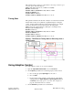
Tuning Gain
This parameter indicates the amount of delay in seconds in the load. This
characteristic of the load or plant has a significant impact on adaptive
control. A larger number indicates a longer delay between, for example
an increase in heater power and an increase in the temperature.
Values: Aggressive (0), Nominal (1), Damped 1 (2), Damped 2 (3),
Damped 3 (4) and Damped 4 (5)
Default: Nominal (1)
Modbus Address (Channels 1 to 32): 46551 to 46682
Parameter Number: 29
LogicPro Driver: Database
LogicPro Address (Channels 1 to 32): 29.1 to 29.32
Figure 1. The Effect of Tuning Gain on Recovery from a
Load Change
Using Adaptive Control
To set up adaptive control on one or more channels:
1. Open the
Spreadsheet Overview screen in ANAWIN3.
2. On the
Inputs spreadsheet for each analog input you have wired:
a. Choose the appropriate
Input Type for the sensor.
b. Choose
Units.
c. For any linear voltage, current, or pulse sensors, set the linear
scaling parameters (
Input Signal Lo, Input Signal Hi, PV Lo,
and
PV Hi). See Setting up User Selectable Linear Inputs on
page 98 of the PPC-2000 User's Guide.
3. On the
Channels spreadsheet for each channel: