Series 1500 ACTUAL ADJUST Ramping and Profiling Microprocessor-Based Control User's Manual Watlow Controls, Inc: 1241 Bundy Blvd., Winona, MN 55987 507/454-5300, Fax: 507/452-4507 W150-MA30-9043 October, 1990 Supersedes: W150-MA20-8843 $10.00 Made in the U.S.A.
How to Use the Manual Use The Manual First... This manual will make your job easier. Reading it and applying the information is a good way to become familiar with the Series 1500. Here's an overview. Starting Out Introduction, Chapter 1, Page 4. Sample Program A Sample Program in Action, Chapter 2, Page 16. Install/Wire Installation and Wiring, Chapter 3, page 26. Programming Technical Reference, Chapter 4, Page 40.
Page 4 4 5 6 7 9 10 12 Item Starting Out with the Series 1500 -Chapter 1 General Description Opening the 1500 Setting the DIP Switches Quick Wire Overview of the 1500 Modes Reading the Displays and Keys Overview of the Software 16 16 16 17 17 18 19 22 22 23 23 24 24 25 Learning the Series 1500: A Sample Program in Action - Chapter 2 ApplePie Sample Program Sample Program Chart Setting Event Outputs Modes of Operation Clear Memory, Set DIP Switches Programming Start Your Program Halt Conditions Ramping Co
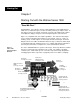
Starting Out Chapter 1 Starting Out with the Watlow Series 1500 "Read Me First." Congratulations, you're about to become a fully-qualified user of the Watlow Series 1500! It is a versatile microprocessor-based control; powerful, yet simple to learn. In this chapter of the user's manual, you'll get an overview of the 1500 and its software. You'll "light" the displays and get a feel for moving through the control functions. Figure 1 is a simplified view of the 1500's capabilities.
Starting Out control because it will move from one process variable to another in a uniform manner. Operator-friendly features include automatic "prompts," or entry codes, to assist you in programming and monitoring. The Series 1500 has other display codes to indicate a variety of alarm conditions about your process. The 1500 also has a "Jump Loop" option for repeating program steps or segments.
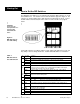
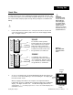
Starting Out How to Set the DIP Switches The Watlow Series 1500 has a set of Dual In-Line Package (DIP) switches on circuit board, A007-1318. The location of the board and switches appear in Figure 2. The switches are clearly numbered; the "ON" direction is indicated by an arrow. Look at the DIP switches from the bottom of the control. You'll see them as they appear below. ! CAUTION: Power must be interrupted before a change in DIP Switch will take effect.
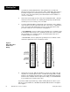
Starting Out Quick Wire You may "power up " the Series 1500 with the following operational check-out. This procedure also prepares you for the Sample Program in Chapter 2. Or, you may skip this section and the sample program, and go directly to Chapter 3, Installation and Wiring. ∫ 1. ∫ WARNING: To avoid potential electric shock use National Electric Code safety practices when wiring and when connecting this unit to a power source and to electrical sensors or peripheral devices.
Starting Out 3. If you did not set DIP Switch #6 in the "ON" position before, do that now: Disconnect power from the unit. Open the 1500, set DIP Switch #6 to ON for a Cold Start. Replace the control chassis in the enclosure. Reapply power to the unit. (This clears all previously entered information from the 1500; it is a "clean" or "cold" start). 4. Now remove power again, open the unit, and set Switch #6 to OFF.
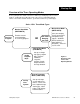
Starting Out Overview of the Three Operating Modes Before getting into the details of the Series 1500's keys and displays, take a look at Figure 5, showing the three different modes. After you feel comfortable with the names of the modes and their functions, go ahead to learn the keys and displays. Series 1500: Four Mode Types Series 1500: Three Mode Types Monitor Data Mode (MNTR DATA) Monitor Data Mode (MNTR DATA) See Your Program Examine current step information in a running program.
Starting Out How to Read the Displays and Use the Keys Here's an understanding of the Series 1500 displays, keys and LEDs. Use Figure 6 to locate the keys, LEDs and displays described here. Try everything! You'll learn quickly how the 1500 works. The detailed overviews in the next section will further your knowledge. Figure 6 Series 1500 Front Panel Components CH SEL key: CHANNEL SELECT--Selects either Channel 1 or Channel 2 for the ACTUAL display.
Figure 6 (Con't) Series 1500 Front Panel Components Starting Out PROG END LED: PROGRAM END-Indicates that the processor has reached the end of the program. CLEAR (erase) key: a. Clears alarm codes from FUNCTION display in MONITOR DATA mode. b. Clears the step in the STEP display in CHANGE DATA mode when the unit is in the HALT condition. c. Clears all 51 programmed steps when the unit in the HALT condition, and in GUARDED ACCESS area of the CHANGE PARAMETER mode.
Starting Out Now that you have a good idea how the 1500's front panel works, look again at the operating modes. This time take a more detailed look. Overview of the Mode Software Again, the Series 1500 has three Operating Modes: Monitor Data, Change Data and Change Parameter. These modes change with the MODE key. They make up the basic software routines that run the Series 1500. Each mode has sub-routines and different prompts that appear in the FUNCTION display whenever you press the FCTN key.
Starting Out Monitor Data Mode (MNTR DATA): Figure 7 Monitor Data (MNTR DATA) Mode Overview Monitoring a Halted Program You may look at any step, but must be in the CHG DATA mode to change the step number. You'll see: • • • • Step type. Ch-1 and Ch-2 set points. Auxiliary outputs programming. Step duration. Monitoring a Running Program You may look at the current step. You'll see: • Ch-1 and Ch-2 current set points. • Auxiliaries programmed ON or OFF. • Time remaining.
Starting Out Figure 8 Change Data (CHG DATA) Mode Overview Change Data Mode (CHG DATA): Three Step Types for Entering Program Data Set Point (SP): a simple, regular profile step. Set Point Step, Program: Jump Loop (JL): a means for jumping to a step out of numerical sequence. Jump Loop Step, Program: Wait for…(WT): a means to wait for a particular condition or time. Wait for Step, Program: This Step# is an SP step. This Step# is a JL step. This Step# is a WT step. Set Point for Ch-1.
Starting Out Change Parameter Mode (CHG PARA) For Entering System-Wide Parameters Figure 9 Change Parameter (CHG PARA) Mode Overview Program Real Time Then proceed to one of three "Guarded Access" areas – code-protected system setup parameters. Program These Parameters: Program These Parameters: Program These Parameters: Set Ch-1 & Ch-2 alarm type and high/low points. Set Recycle Option (program repeat). Set up Ch-1 and Ch-2 high and low ranges. Leave "Guarded Access.
Sample Program Chapter 2 Learning the Series 1500 — A Sample Program in Action This chapter will guide you through an easy sample program for the Series 1500. You can quickly grasp the necessary terms and concepts by entering and observing this exercise. If you feel that your knowledge of programmable controllers does not require a sample program to learn the Series 1500, feel free to skip this chapter. In the Technical Reference section (Chapter 4), you will find details on all material here.
Sample Program Perform Steps 4-6 Th Temp/ %RH Step 1 Step 2 (Wait) Step 4 Step 3 Step 5 Chart 1 Series 1500 Sample Program Chart 90% RH 74% RH Temp/ %RH Step 1 Step 2 (Wait) Step 4 Step 3 Step 5 90% RH 74% RH * 400°F 50%RH 275°F Setting Event Outputs To make the pie process even more automated, you have your toppings — sugar, cinnamon and nutmeg—connected to solenoid dispensers controlled by the 1500's "Event Outputs.
Sample Program Before you begin entering the program, notice three small lights (LEDs) on the bottom half of the 1500's front panel. They are labeled "MNTR DATA" (Monitor Data), "CHG DATA" (Change Data), and "CHG PARA" (Change Parameters). Press the MODE key to move through these three modes as you read about each one. Another LED, labeled "TIME" indicates when time is being displayed. "MNTR DATA": While a program is running, you'll want to observe what's happening.
4. Press the ENTER key: the display will flash, then it will change to “MN.” 5. Use the UP/DOWN keys to place the correct value for minutes into the Data Display; then press ENTER. 6. The display will show “SC” (seconds): again use the UP/DOWN keys to place seconds into the display and then press ENTER. 7. Press the FCTN key several times until the TlME LED is lit (along with the CHG PARA LED). You should now see the correct real time on the display, with the seconds counting up.
Sample Program 4. We suggest that you enter a time one hour from right now. Changing this time later is a simple matter. You go to the CHG DATA mode with "WH" displayed and then enter the new time. Select hours (0 to 23) and press ENTER. 5. Also enter the "WM" (minutes) and "WS" (seconds). Select minutes, press ENTER. Wait a moment for the display to change, then select seconds and press ENTER. 6. You have completed entering Step #1 as a "Wait Step." The display should now read "01 NX 0002.
Programming Steps 3 through 6 Now that you see how it’s done, enter the data for Set Point Steps #3,4,5, & 6. But, be sure to stop and then return to these instructions when the display reaches “07 SP.” This is because you will be looping through Steps #4 through #6 three times. Refer to the table below for Steps #3,4,5 and 6. FCTN I STEP #2 I STEP#3 I STEP #4 I STEP#5 I Step#6 Table 3 Sample Program Steps Programming Step 7, a Jump Loop Step You now have Steps #1-6 programmed.
Almost Ready to Run Remember that Step #1 was a “Wait Step.” Even though you press the “RUN” key, you won’t see any action until the time you programmed into Step #1. You may want to go back and adjust that time to a different value. Therearevarious ways to get back to Step #1 in CHG DATA mode. Your display is now reading “08 NX 0009”; it is waiting for you to continue programming or monitoring. Use the DOWN key to put “0001” in the Data display and press ENTER.
C. While in the HALT condition, the Series 1500 maintains the Set Points and Event Output conditions from the step it was in when it was halted, or from last step before a “Blank Step” halted the control. If you restart the control, having made no change to the step data, the 1500 will complete the step from the time it stopped. If you change data, the step begins from beginning. D.
C. In your sample program’s Wait Step, you used “Wait for time” because you aren’t connected to a variable oven yet. A more common use of the Wait Step could be as follows: In Step #2, you have allowed exactly four minutes to reach 400°, 90%RH. Depending upon your system, this may either be impossible to do, or you may reach the desired conditions much earlier than that. This could result in bad apple pies.
Sample Program However, remember that Step #1 is programmed as a "Wait Step," so it will wait until the same time tomorrow. Since you now know what a Wait Step does, you may want to reprogram Step #1 as a simple "Set Point" step so that you can view the Recycle action. If you do decide to reprogram Step #1, then read the following items. • 1500 You cannot alter data or parameters while the program is running. The must be in the HALT condition.
Installation-Wiring Chapter 3 How to Install and Wire the 1500 This chapter tells you how to install and wire the Series 1500. There are also some suggestions for sensor installation. Also, be sure to look at the noise reduction guidelines before making your panel cutout. Sensor Installation Guidelines Temp-RH In this 1500 configuration, a dry bulb RTD measures temperature on Channel 1. A wet bulb RTD, in combination with the dry bulb RTD, senses relative humidity on Channel 2.
Installation-Wiring Use distilled water to avoid mineral deposits on the wick that can change the %RH reading. The wicking distance should be as short as practical. The cotton wick must be free of any sizing and starch. The "float valve-trough" systems should also remove the water when the ambient temperature goes below freezing or above boiling. To obtain valid %RH readings, air flow past the %RH sensor must be sufficient to evaporate the maximum amount of water from the wick without drying it out.
c. Shielded RTD sensor with the shield terminated to the Series 1500 case and to an existing ground plane. 2. Physical separation and wire routingmust be given careful consideration in planning the layout of the system.. For example, A.C. power supply lines should be bundled together and physically kept separate from input signal lines (very low power level). Keep all switched output signal lines (high power level) separate from current control loop signals (low power level). 3.
Input Power Wiring Installation-Wiring Microprocessors are in a way like trout… They require a clean environment to be successful and to prosper. A clean environment means on one level an environment that is free of excessive dust, moisture and other airborne pollutants. But primarily it means a "clean" source of input power from which to base all its operations.
Installation-Wiring keep the line "clean." Do keep low power control wires physically separated as far as possible from line voltage wires. Also keep all controller wiring separate from other nearby wiring. Physical separation is extremely effective. A 12 inch minimum separation is usually effective. Do use common mode, differential mode or a combination of the two filters wherever power may have electrical interferences. Do cross other wiring at 90° angles whenever crossing lines is unavoidable.
Installation-Wiring Noise Suppression Devices Available from Watlow Watlow Winona stocks a few key noise suppression parts. You may order these by calling your local Watlow distributor. Item Electrical Ratings Part Number Common Mode Line Filter 250V, 3 Amp 0804-0196-0000 Differential Mode Line Filter Refer to the islatrol listing above.
How to Eliminate Noise Watlow Part Number for Quencharc: 0804-0147-0000 1. Use “Quencharcs” to suppress noise generated by devices such as relays, relay contacts, solenoids, motors, etc. A Quencharc is a simple filter device using a .1µf, 600 volt, non-polar capacitor in series with a 100 ohm, 1/2 watt resistor. The device can be used on an A.C. circuit to effectively dampen noise at its source. For a D.C. circuit, use a diodex across the inductive load coil to dampen noise.
Installation-Wiring 8.68 1.180 7.000 0.500 Figure 13 Unit and Panel Cutout Dimensions 5.375 ± 0.015 Bezel Mounting bracket Note: All dimensions in inches. 5.433 SQ. MIN. 5.472 SQ. MAX. Your Panel Thickness: or 5- 7/16 Nominal 0.06 to 0.25 Note: All dimensions in inches. 6.0 6.
Installation-Wiring Installation Procedure ” WARNING: To avoid electric shock, make all connections on the terminal strips on the back of this control before connecting power to the unit. Also disconnect power before opening the Watlow Series 1500. ! CAUTION: All wiring and fusing should conform to the National Electric Code and to any locally applicable codes as well. 2 CAUTION: Before connecting the Series 1500 to a data communications network, remove power from all devices on the network. ! 2.
Installation-Wiring SIGNAL CONDITIONER RTD Version Analog Signal Common % RH Analog Output Analog Output Ch-2 °F (Wet Bulb) Figure 14 Signal Conditioner Connections and Jumpers.
Installation-Wiring Fig. 15 Event Output, Remote Hold Input and Event Input Connections for Dual Solid State Relay Version Event Input/Output, 0.5 Amp Solid State Relay Model # 150_ - _ _ _ 1 - _ _ _0 Event Common 13 14 15 16 17 18 19 20 21 22 23 24 CH-2, Event 4 Load CH-2, Event 3 Load NOTE: CH-2, Event 2 Load Event outputs can be powered by a line (up to 240VAC) independent of the control input. The event outputs can conduct up to 0.5A each.
Installation-Wiring Event Input/Output, Open Collector Model # 150_ - _ _ _ 2 - _ _ _0 +10 Unregulated Supply Event Common 13 14 15 16 17 18 19 20 21 22 23 24 CH-2, Event 4 Load CH-2, Event 3 Load CH-2, Event 2 Load CH-2, Event 1 Load CH-1, Event 4 Load CH-1, Event 3 Load CH-1, Event 2 Load CH-1, Event 1 Load Remote Hold Input Event Input Digital Common Fig.
Installation-Wiring Figure 17 Power Supply Input, CH-1 & CH-2 Output Connections Power Supply Input, Temp & RH Control Output 115VAC L2 For 115VAC control operation, install a jumper wire from Terminal 32 to Terminal 35, and a separate jumper wire from Terminal 33 to Terminal 36. Bring line power in to Terminals 32 (L2B) and 36 (L1A). Connect the line ground wire to Terminal 34. CHASSIS GROUND L1 CAUTON: Fuse load and power outputs properly.
RS-423A (RS-232C) Installation-Wiring Signal Common Transmit (Data Out) Jumper Pin 11 to Pin 3 Serial Port Groun Jumper Pin 3 to Pin 11 Receive (Data In) Figure 19 RS-422/423 Interface, Pin Designations and Jumper. Series 1500 DB-15 Female with respect to the Series 1500 RS-422A Tran + Tran (Serial Port Common) Rec + Rec - You must also set the RS-423/RS-422 Jumper for a communications interface. Put the jumper on W423 for RS-423, or on W422 for RS-422.
Programming Chapter 4 Technical Reference Technical Reference This section of the Series 1500 manual is compiled for easy reference and rapid information retrieval. Notice the page headings as you thumb through the section; they will assist you in finding what you need. How to Program the Series 1500 Here's how to enter a program into the Series 1500 through the front panel. If you haven't already read it, you'll find a good sample program in Chapter 2 which will also teach you the programming process.
Technical Reference Programming CHG DATA Normally, the 1500 should be in the Warm Start condition. In Cold Start, all program information will be lost when power is applied to the unit. DIP Switch #7 sets the temperature scale at °C or °F. DIP Switch #8 is not used, set it to the OFF position. Recycle Option You may request that your program repeat indefinitely by selecting RC=1 in the GA = 6 area of the CHG PARA mode.
Technical Reference Press to light CHG DATA LED. S e r i e s 1500 D i s p l a y s Press to select the Step Type you want: SP, JL, VVT or NX. Press enter to select individual prompts. STEP FUNCTION DATA LA I = Blank Display Press to select values. m = Step Number W 1-1 = Next Step in Sequence Press to enter data into memory.
Technical Reference At the end of a program, or in a hatted condition, the Series 1500 wiIl continue to hold set points and Event Outputs at the same states they were in at the end of the final step or when the program was halted. Example: If you press the RUN/HALT key at 1-1/2 minutes into a step, the control would hold an oven at that step’s set points and Event states.
Technical Reference Jump Loop Step Here's an example: • You start a Step #4 at 400° (Step #3's set point), and ramp uniformly down to 275° (Step 4's set point). • If you "loop back" from Step #6, your starting point will be the Step #6 set point and not the Step #3 set point. You will be ramping to 275° from a different starting point. • You might want to jump back to an earlier step to reach a full 400° through Step #3 before you start Step #4.
Technical Reference WT (Wait) Step Programming This submode allows the Series 1500 to wait for Channel 1 and/or Channel 2 actual process inputs and/or the real time of day. You can wait for one or two of these conditions, or all of them. If you don't need one wait condition, just press the FCTN key, and the next Wait prompt will appear. • With W1 (Channel 1 Actual) select the Ch-1 Wait set point and press ENTER. • With W2 (Channel 2 Actual) select the Ch-2 Wait set point and press ENTER.
Technical Reference Altering a Program 1 NOTE: If you have the opt ional battery You cannot alter data or parameters while the program is running. The 1500 must be in the HALT condition. backed clock, the time may already If you want to move to a diierent Step # to see what is programmed there and then modify that step, enter the CHG DATA mode. Then press the FCTN key until the “NX” appears in the Function Display. Place the Step # into the Data Display and press ENTER. be correct. .
Technical Reference Guarded Access minutes with the UP/DOWN keys. Press ENTER. The prompt SC will appear. Select correct seconds with the UP/DOWN keys. Press ENTER; GA will appear. GA (Guarded Access) Programming The Guarded Access parameters control the process limits. The three GA parameter loops are restricted to operators by special codes. The Guarded Access codes prevent inexperienced or unauthorized operators from changing the parameters. The GA prompts appear in the Guarded Access Charts (p.
Guarded Access Technical Reference • RT (Rate) Select a rate value with the UP/DOWN keys. Then press ENTER; press FCTN. • Rb (Rate Band) Rate band defines where the rate function will occur. The Rate Band will occur at one to seven times the proportional band. With a "0" entry, rate is always in effect. Select a rate band value with the UP/DOWN keys. Then press ENTER; press FCTN. • CT (Cycle Time) Enter a cycle time value with the UP/DOWN keys. Then press ENTER; press FCTN.
Technical Reference Alarms The 1500 system provides four basic alarm conditions in each of the two control channels. They are, with mnemonic abbreviations: Upper Process - UP Lower Process - LP Upper Deviation - Ud Lower Deviation - Ld A “process” alarm, you will recall, is available at an absolute process level. A “deviation” alarm, on the other hand, is linked to the process set point.
Technical Reference Alarm Display Codes h in the FUNCTION display, indicating the type of alarm. These alarm messages are listed below. The first two are operational alarms that have no effect on alarm/event outputs. j NOTE: An Al power interrupt alarm will always flash until an operator presses the CLEAR key (or sends ALMOO), regardless if aIarms are latched or unlatched.
Technical Reference Event Outputs One of the most versatile features of the Series 1500 is its capability for event outputs. An “event output” is simply a preprogrammed ON/OFF event. There are eight total, four for each channel during each individual step. The event may turn any number of peripheral devices ON or OFF to assist you in controlling your process, system or environment.
Technical Reference Analog Retransmit Outputs Each sensor input signal level is made available at an “Analog Retransmit” output for chart recording or other uses. See Terminals 1,2,3,4 and 11, page 35. The scaling of these outputs varies with sensor type and function. The following is a summary of. the scaling: RTD Units -0500VDC 0.000VDC +5.000VDC = = = O.OOOVDC = 1.250VDC = 2.500VDC = ° F -1 00.0°F 0.0°F 1 000.0°F Ei=uum 0°C 250°C 500°C If using %RH 0.000VDC 0.500VDC 5.000VDC = 0.0%RH = l00.
Program # GA Cod Ch Pmpt Programmer Parameter Date 1 Default High Low UP Ch - 1 Upper Process Alarm 999 538 LP Ch - 1 Lower Process Alarm -99 -99 999 538 -999 -538 101 999 538 -001 -99 -99 101 999 538 -101 -999 -538 0004 0001 0001 OO(IO 0005 0000 0000 -99 0001 0001 Cl Ud Ch - 1 Upper Deviation Alarm Cl Ld Ch - 1 Lower Deviation Alarm C2 UP Ch - 2 Upper Process Alarm C2 LP Ch - 2 Lower Process Alarm C2 Ud Ch - 2 Upper Deviation Alarm C2 Ld Ch - 2 Lower Deviation Alarm 1H 1H 5.
Technical Reference Use this chart to determine parameter ranges, limits and default settings. Then enter your setting for each parameter. Make a photocopy of the chart and enter values for each program you use. Program # System G A Ch Pmpt Programmer Parameter Date Default Range Your .
Technical Reference Use this chart to determine parameter ranges, limits and default settings. Then enter your setting for each parameter. Make a photocopy of the chart and enter values for each program you use. Program # . System Date Programmer Series 1500 DIP Switch Settings Sw-Position #1 -ON #1 - OFF ##2 - ON #2- OFF #3-ON #3-OFF #4-ON #4 - OFF #5 - ON #6 - ON 1 #6 - OFF #7-ON #7 - OFF #&OFF Function Setting Event Output #4 for both Ch-1 and Ch-2 are alarm outputs.
Technical Reference Programming Chart Make photocopies of this page and the previous page, then record your parameters and entire program step by-step. Prog. No.
Technical Reference Programming Chart Make photocopies of this page and the previous page, then record your parameters and entire program step by-step. Prog. No.
Technical Reference Tuning For optimum control performance, it is necessary to tune the Series 1500 to your thermal system. At this point you should already have a program profile entered into the 1500. This profile needs to be as nearly typical of your system requirements as you are able to predict. Recommended Tuning Reference There are a number of quality references on the art of tuning electronic controllers to the systems they control.
Technical Reference Manual Tuning For optimum control performance, tune the 1500 to the themal system. The tuning settings here are meant for a broad spectrum of applications; your system may have somewhat different requirements. Refer to the key flow charts, diagrams and definitions on Pages 42 - 61 for prompt location and description. Repeat this tuning procedure for both Channel 1 and 2. 1 NOTE: When tuning in the Heat mode, use H where X appears. When tuning In the Cool mode, use C where X appears.
Technical Reference to Run and Halt A Program Here is how to run and halt Series 1500 programs. How to Run a Program When you have all program steps defined and entered, press RESTART to return the processor to Step 01. Then press RUN/HALT to begin the program. How to Halt a Program To stop the program, press RUN/HALT. The PROG HALT LED will light. The program stops in the current step. The processor holds all values for the outputs as they were at the moment the program stopped.
Data Communications, Commands and Syntax In this section you’ll learn the Series 1500 data communications. See Figure 14 in Chapter 1 for RS422 and RS423 pin designations, and also for locating and making the required RS422/423 jumper selection. The Series 1500 data communications package provides you with a foundation for a sophisticated communications system based on your system needs and your software development.
Technical Reference Command Rules The following listing shows the command and the typical Series 1500's response string. The labels beneath each parameter in a command or response string are here for your information only: they will not appear on your computer screen. . A command word with a question mark is a direct request for a response, a query. . The__'s in the pages that follow are the number of character positions in a parameter available for entry or response. .
Technical Reference Command Words The Series 1500 recognizes and responds to the following list of syntactical command words through a serial communication interface. ACT? Requests actual process inputs. MTR? Requests information on the current step. ST?? Requests programmed information for a step. STP Enter step information. PTR? Request real time of day, and high and low set point limits. PTR Enter real time of day, and high and low set point limits.
Technical Reference Command Words and Syntax Here is a list of the command words with the syntax. Limits for all parameters are in the Guarded Access and General Parameters Charts located in this section of the Series 1500 manual. J NOTE: Decimal points in general are not available for the Series 1500 T/C version. See the T/C charts on pp. 50 and 52. Requests the current ACTUAL process Inputs. ACT? Sample Response: 2050 0820 ---.- - - -.Ch-1 Actual Ch2 Actual Monitors information on the current step.
Technical Reference STP? -- Requests.the programmed informatlon for Step# - - . The first response parameter is the Step Type: 0000 = Blank Step 0001 = Set Point Step 0002 = Jump Loop Step 0003 = Wait For Step Sample Transmission: STP? 22 Blank Step - STP? l =Unprogrammed parameter 0000 **** **** Step Type Ch-1 set Ch-2 set Point Point Set Point Step - STP? 0001 — — —.— ———.— Step Ch-1 Set Type Point Ch-2 Set Point ———— ———— Ch-1 Events ———— al-2 Events ———— —— Hr. Mn.
Technical Reference Walt Step- STP? *=Unprogrammed parameter -99 0 0 Step 0 -99 3 3200 ---.- Wait For Type - °F --.- - - - * * * ---- ---- Wait For Wait For Event Wait_ Ch-2 . Ch-1 l ---- Wait For Minutes wait For RealTime Sample Response: 0003 1234 0840 0001 **** 0015 0010 0030 l Program a step. STP The first parameter entered after the step number is the Step Type.
Technical Reference Jump Loop Step - STP Sample Transmission: STPl202100004 Wait Step - STP l = Unprogrammed parameter 999.9 03 -99.9— — 999.9 —.— °F — . — —— — — Step Ch-1 set S t e p Type # ———— Ch-2 set Point Point * —— Wait For Evsflt —— —— Hf. Mn. Wait For Real Time of Day Sample Transmission: STP 14 03 2100 0900 1*08 30 00 PTR? Requests real time of day, and upper and lower set point limits.
Technical Reference TIM? _D HR Requests real time of day only -- -- SC MN Sample Response 12 34 56 Enter real time of day only TIM MN SC SampleTransmission: TIM 23 59 59 LIM? Requests upper and lower set point limits — ——.— --CH-1 Upper Limit — ——.— --- .- Ch-1 Lower Limit — ——.— --- — — — ..— CH-2 Upper Limit CH-2 Lower Limit --- w Sample Response: 8765 4321 1234 -123 LIM Enter upper and lower set point limits ---.Ch-1Upper Limit ---.Ch-1 Lower Limit ---.CH-2Upper Limit ---.
Technical Reference RCY? Request the Recycle option -Recycle Sample Response: 01 RCY Enter the Recycle option Sample Transmission: RCY O1 GAI? Single PID: ———— - —M--B—.—— — —-d-m .—— — —---—— ———— w-w- Chl Reset Chl Prop. Band Chl Rate Chl Rate —__d_ —.—— Chl — —.— — Chl Cycle Time Heat Rate Time Sample Response: 0048 0012 0034 0003 0029 0021 0012 Dual PID: —— —— — —.— — -----.-—— Ch1 Prop. Band Heat --.--— —-—-—- - — —.
Technical Reference GA2? Sample Response: 00480012003400030029 00210012 Dual PID: ---v -dee ~~*~~ Ch2 Prop. Band Heat Ch2 Rate Reset we-- ~~~~ ---*- Rate CYde lime Heat Heat : M--d- - - - Calib. offset Prop. Band Reset Rate -v-m - - - Ch2 Rate We lime Sample Response: 0048 0012 0034 0003 0029 0021 0012 0058 0021 0043 0000 0020 GA2 Single PID: ---w v-.-Ch2 Prop. Band - - - - - - - - --*-- Ch2 Rate Band Ch2 Rate Reset Cycle Time ---*Ch2 Dead w-v*Calib.
Technical Reference ALM? Request current alarm code information. Sample Response: 0018 Note: These alarms are additive and may occur in any combination. To decode, use the following list. Subtract out the largest possible integer first, then the next largest possible integer, and so on. The integer 16 is the largest possible integer to subtract out, leaving a remainder of 2. The integer 2 stands alone. Thus Alarm Codes 16 and 2 are now present in the system.
Technical Reference Request values for the process and devlatlon alarm set points. PDA? C-1 Upper Process Ch-1 Lower Process Ch-1 Upper Deviation Ch-1 Lower Deviation Ch-2 Upper Process Ch-2 Lower Process Ch-2 Upper Deviation Ch-2 Lower Deviation Sample Response: 0999 -099 0555 -555 0101-001 0999 -099 0999 -999 PDA Enter values for the process and deviation alarm set points.
Technical Reference Data Communication Error Codes When you query “ERR?” using the correct protocol, a Series 1500 linked to a computer will respond with these 3-digit data communications error codes. The code will appear on your computer screen. A definition listing for each code is in the right-hand columns below.
Technical Reference Bad Sensor Bad Sensor Indication and Troubleshooting Indication When a bad (open or shorted) sensor occurs for Ch-1 or Ch-2, the ACTUAL display will show "- - - - ". The Series 1500 control outputs in both channels de-energize when a bad sensor occurs. The events outputs remain energized. Bad sensor on Ch-1 will produce alarm codes A2 and A4. Bad sensor on Ch-2 will produce alarm codes A6 and A8.
Technical Reference Field Calibration Field Calibration Procedure ”1 — RTD Calibration — The Series 1500 is shipped totally calibrated from the factory; it does not need field calibration, and will not except in unusual circumstances. This calibration procedure will enable you to calibrate the Series 1500 low voltage analog input and output signals for accuracy. Equipment Needed ” 1 1. Two 100 ohm decade boxes. 2. Two board connectors, Watlow P/N Z100-0285-0000. 3. Digital voltmeter.
Technical Reference Field Calibration Calibrate Channel 1 °F Output 7. Remove (+) plus lead from E-120 and connect to Term. 4. Set Ch-1 input to (92.93) [93.03] ohms. Adjust Ch-1 SC-Lo pot for 0.000V on DVM. Ch-1 Actual should be 000.0 ± 0.5°F (-18°C). 8. Set Ch-1 input to (294.91) [291.56] ohms and adjust Ch-1 SC-Hi pot for 4.950VDC. Actual should read 990.0° ± 0.5°F (532°C). 9. Repeat Steps 7 and 8 until all the readings are correct with no further adjustment necessary. 10. Set Ch-1 input to (199.
Technical Reference d Calibration Field Calibration Field Calibration Procedure — Thermocouple Calibration — The Series 1500 is shipped totally calibrated from the factory; it does not need field calibration, and will not except in unusual circumstances. This calibration procedure Equipment Needed ” 1 1. One Millivolt Source (two if doing both channels simutaneously). 2. Two board connectors, Watlow P/N Z100-0285-0000. 3.
Technical Reference Field Calibration bration Calibration NOTE: The following procedure applies to all three T/C types, although the Input/Output values may differ between types. Use the values corresponding to 1. Document DIP Switch settings and values in Guarded Access, pages 54 & 56. 2. Set Series 1500 DIP Switches 3 & 6 ON, all others OFF. 3. Set mV Source as follows. Type Setting J K R -0.885 mV, (0°F) -0.692 mV, (0°F) +2.282 mV, (550°F) 4.
Reference Field Calibration 10. Repeat Steps 5-8 until all the readings are correct with no further adjustments necessary. 11. Turn power OFF. Set DIP Switch #7 ON (deg. C). Move DVM (+) plus lead to Signal conditioner connector terminal 11 (terminal 4 for CH-2). Turn power back ON. 12. Set mV Source as follows, and adjust "Deg. C Lo Pot" for the corresponding DVM reading. Actual should read the value shown. Type mV Source DVM Reading Actual Reading J K R -0.885mV, (0°F) -0.692mV, (0°F) 2.
Technical Reference Specifications General Features . . . . . . . . . Dual channel closed loop control. Temperature and relative humidii. 51 time-based steps for ramping. 8 event outputs per step. 1 event input. 1 remote hold input. Data communications interface optional. Fully programmable parameters. Membrane faceplate. User-friendly, 1/2 DIN plug in chassis. Three year warranty. • . Control Mode Microprocessor-based user selectable modes. Dual channel with dual control outputs per channel.
Technical Reference Temperature ranges: .. -100 -99.91400°F 999.9 999.9 °F 760°C -73 to or -73 to 1371 °C K t/c: -100 to 2500°F o r R t/c: 500 to 3200°F or 260 to 1760°C RTD._* -99.9 to 9999°F or _-99.9 to 537.7% T/C inputs must be ungrounded. %RH ranges (on channel #2 only) and user selectable. Range limits are 0.0 to 100.0% RH Input types: . RTD: % RH IS based upon Channel #1 RTD as dry bulb and Channel #2 RTD as -99 -99 3200 °F 0-5/DC:’ Direct % RH signal on Channel #2.
Technical Reference Series 1500 B = Standard C = Battery-backed real time clock 1 2 3 4 5 = = = = = Two RTDs One RTD &One 0-5VDC Two J t/c Two K t/c Two R t/c ChanneIs AA BB 1 & 2 Control Outputs = = 2 S.S. relays, 0.5A. 2 S.S. switches, 10VDC, 5mA Auxilliary Outputs/lnputs 0 = None 1 = 2 = 8 discrete outputs: S.S. relays, 0.5A and 2 dry-contact inputs (event & remote-hold) 8 discrete outputs: S.S.
Technical Reference Technical Service If Something Goes Wrong The Series 1500 is a designed for long life and durable service. If, however, something should go wrong, call Watlow at 507-454-5300, and ask for an application engineer. We’ll help you with the problem right on the phone. Warranty Information The Watlow Series 1500 is warranted to be free of defects in material and workmanship for 18 months after delivery to the first purchaser for use, providing that the unit has not been misapplied.
Technical Reference Shipping Claims When you receive your Watlow Series 1500, examine the package for any signs of external damage it may have sustained enroute. If there is apparent damage either outside the box or to its contents, make a claim with the shipper immediately. Always save the original shipping carton and the packing material. Watlow Winona, Inc. Watlow Winona, Inc. is a division of Watlow Electric Manufacturing Company of St. Louis, Missouri.
Glossary This glossary includes general thermal system control terms; not all are used with the Series 1500. Actual display data: Displayed information which gives the operator/programmer real or “actual” data, i.e., actual time of day, actual process temperature, or actual process relative humidity,etc.See“Programmeddisplaydata.” Alarm: A signal,generated by the Series 1500, warningthe operator that the process hasexceededorfallen belowthe alarm setpoint. Anti-reset: Control band.
Derivative: Same as “rate.” Anticipatory action that senses the rate of change of temperature, and compensates to minimize overshoot. Deviation: The difference between the value of the controlled variable and the value at which it is being controlled. DIP switch: Dual In-line Package (ON/OFF) switch. Displaycapability: In a digital indicating instrument, the entire span that can be indiiated if fully utilized. Droop: Difference in temperature between set point and stabilized process temperature.
Overshoot : Condition whereby temperature exceeds set point due to initial power up or process changes. P control Proportioning control. Parameter: Any of a set of physical properties whose values determine the response of an electronic control to given inputs. PD control: Proportioning control with rate action. PI control: Proportioning control with auto-reset. PID control: Proportioning control with auto-reset and rate.
Restart: To begin to control a thermal system again, after stopping control and holding the process variable at a fixed value. A “restart” may occur with newlyprogrammed information in microprocessor-based controls. RTD: Resistance Temperature Detector. Resistive sensing device displaying linear resistance versus temperature characteristics. Displays positive temperature coefficient. Set point: Intended value of the process variable.
A Alarms, 49 Alarm Codes, 50 Almost Ready to Run, 22 Analog Retransmit, 52 B Before You Begin (Programming), 18 Bad Sensor, 74 C Change Data Flow Diagram, Fig. 20,42 CHG DATA Overview, Fig. 8,14 Change Parameter Flow Diagram, Fig. 21,46 CHG PARA Overview, Fig. 9,15 Cycle Time, 48 D Data Comm. Commands and Syntax, 61 Data Comm. Error Codes, 73 Dimensions, Unit and Panel Cutout, Fig.
Series 1500 Quick Reference MODE FCTN = Set Point Step: Change Data Mode (CHG DATA) SP Program set points, events and time. Selects MNTR DATA, How to Get Around in the Series 1500 Software CHG DATA or CHG PARA Mode. JL=Jump Loop Step: Program step # to jump to, and # of times to repeat that step. Selects any prompt in a mode. WT=Wait Step: Program a step to wait for… Ch-1 condition, and/or CH-2 condition, and/or an event, and/or a real time (hr, min, sec). Selects values for the DATA display.