
Manual

WATLOW Series 1500 User's Manual 3
Contents
Contents
59 Restarting a Program
59 Remote Hold Input
60 Data Communications
60 Communication Parameters
60 Protocol
60 Command Rules & Words
61 Syntax
73 Data Communication Error Codes
74 Troubleshooting
75 Field Calibration Procedure
80 Specifications
82 Model # Information
83 Technical Service
83 Warranty Information
83 Returning Merchandise
84 Shipping Claims
85 Glossary
89 Index
90 Quick Reference
Figures
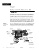
4 Series 1500 Input and Output Overview 1
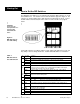
6 DIP Switch Location and Setting 2
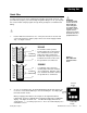
7 Quick Wire AC Power Connection 3
8 Quick Wire Simulated Sensor Wiring 4
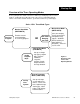
9 Overview of the Series 1500 Operating Modes 5
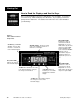
10 Series 1500 Front Panel Components 6
13 Monitor Data (MNTR DATA) Mode Overview 7
14 Change Data (CHG DATA) Mode Overview 8
15 Change Parameter (CHG PARA) Mode 9
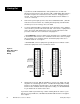
31 Differential Mode Filter Diagram 10
31 Common Mode Filter Diagram 11
31 Differential Common Mode Filter Diag. 12
33 Unit and Panel Cutout Dimensions 13
35 Signal Conditioner Connections and Jumpers 14
36 Event Output, Remote Hold Input, Event Input
Conn. for Dual Solid State Relay Version 15
37 Event Output, Remote Hold Input, Event Input
Conn. for Dual Solid State Switch Version A 15
36 Power Supply Input, Temp & RH Output Conn.
for Dual Solid State Relay Version 16
37 Power Supply Input, temp & RH Output Conn.
for Dual Solid State Switch Version A 16
38 Power Supply Input, CH-1 & CH-2 Output Conn. 17
38 Wiring to Disable Channel 2 18
39 RS-422/423 Pin Designations and Jumpers 19
42 Change Data Mode Flow Diagram 20
46 Change Parameter Mode Flow Diagram 21
Tables
6 DIP Switch Position and Function Table 1
17 Sample Program Event Outputs Table 2
21 Sample Program Steps Table 3
31 Noise Suppression Device Ratings Table 4
Charts
17 Series 1500 Sample Program Chart Chart 1
53 RTD Guarded Access Chart Chart 2
54 T/C Guarded Access Chart Chart 3
55 RTD General Parameter Chart Chart 4
56 T/C General Parameter Chart Chart 5
57 Programming Chart Chart 6
Page Item
4 Starting Out with the Series 1500 -Chapter 1
4 General Description
5 Opening the 1500
6 Setting the DIP Switches
7 Quick Wire
9 Overview of the 1500 Modes
10 Reading the Displays and Keys
12 Overview of the Software
16 Learning the Series 1500: A Sample Program
in Action - Chapter 2
16 ApplePie Sample Program
16 Sample Program Chart
17 Setting Event Outputs
17 Modes of Operation
18 Clear Memory, Set DIP Switches
19 Programming
22 Start Your Program
22 Halt Conditions
23 Ramping Conditions
23 Wait Step
24 Jump Loop Step
24 Recycle
25 Interactive Changing Set Points & Events
26 Install and Wire the Series 1500 - Chapter 3
26 Sensor Installation Guidelines
27 Event Input and Remote Hold Input
27 Noise
29 Input Power Wiring
32 Eliminating Noise
32 Opening the 1500
34 Installation Procedure
34 Electrical Connections and Wiring
40 Technical Reference - Chapter 4
40 How to Program
40 Select the Proper DIP Switch Settings
41 Programming CHG DATA
42 Halt Conditions
43 Set Point Step Programming
44 Jump Loop Step Programming
45 Wait Step Programming
45 Next Step Programming
46 Altering a Program
46 Programming CHG PARA
47 Guarded Access Programming
49 Alarms
49 Alarm Options
49 Event Alarm Output Option
49 Latching Option
49 Alarms
50 Upper/Lower Set Point Limits
51 Event Outputs
51 Event Input
51 Remote Hold Input
52 Analog Retransmit Outputs
53-56 RTD and T/C Guarded Access/Parameter Charts
57 Programming Chart
58 Tuning
58 Initial Settings
58 Simple ON/OFF Control
59 Run and Halt a Program
59 How to Run a Program
59 How to Halt a Program