
Manual

Starting Out
6 WATLOW Series 1500 User's Manual
Starting Out, Chapter 1
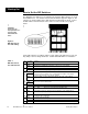
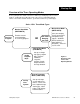
How to Set the DIP Switches
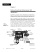
The Watlow Series 1500 has a set of Dual In-Line Package (DIP) switches on circuit
board, A007-1318. The location of the board and switches appear in Figure 2. The
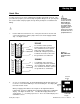
switches are clearly numbered; the "ON" direction is indicated by an arrow. Look at
the DIP switches from the bottom of the control. You'll see them as they appear
below.
!
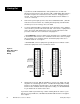
Set the DIP switches according to Table 1 below. Make your initial choices now; you
may always return to change them later. Set DIP Switch #6 ON for a "Cold Start."
Sw Position Function
#1 ON Auxiliary (Event) Output #4 for both Ch-1 and Ch-2 are alarm outputs.
OFF Auxiliary (Event) Output #4 for both Ch-1 and Ch-2 are event outputs.
#2 ON Alarms are latching (displayed until cleared manually).
OFF Alarms are non-latching (displayed only as long as alarm condition exists).
RTD Unit Only
#3 ON The Ch-2 sensor is an RTD sensor. Jumpers W151 and W153 on the Signal
Conditioner board (A007-1316) must be installed.
OFF The Ch-2 inputs is a 0-5V signal representing 0-100% RH. Jumpers W150
and W154 on the Signal Conditioner board (A007-1316) must be installed.
T/C Unit Only
#3 ON Not Used. Set in the ON position.
#5 ON Factory use only. Must be in the ON position.
#4 ON Dual PID per channel - #4 OFF Single PID per channel.
#6 ON Cold Start on power-up. (Memory cleared, parameters set to default values.)*
OFF Warm Start on power up. (Programmed values are retained for all parameters.)*
#7 ON °C function after a Cold Start.
OFF °F function after a Cold Start.
#8 OFF Not Used. Set in the Off position.
!
CAUTION:
Power must be
interrupted before a
change in DIP
Switch will take
effect.
Figure 2 -
DIP Switch Loca-
tion and Setting
Table 1-
DIP Switch Posi-
tion and Function
For further Warm and Cold Start information, see the Technical Reference, Chapter
4.
*
Control Chassis - Bottom View
DIP
Switches
A007-1318
Board