Series 365 ISO 9001 Registered Company Winona, Minnesota USA User’s Manual 1/16 DIN Temperature Control Watlow Controls Watlow Controls, 1241 Bundy Blvd., P.O. Box 5580, Winona, MN 55987-5580, Phone: 507/454-5300, Fax: 507/452-4507 0600-0012-0001 Rev B March, 1998 Supersedes (1308) $5.00 Made in the U.S.A.
Description The Series 365 is a 1/16 DIN factory-selectable analog latching limit, ON/OFF or PI control. The control operates from a thermocouple or RTD input and is available in several thermocouple ranges including Types J, K, T, R, S or Platinel II thermocouple. The 365 has an integral setpot with a front panel reset switch, and a front panel LED indicator for output status. In addition to the internal reset switch, a customer supplied remote reset switch can be used with the limit control only.
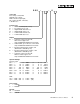
Model Number 365_-____-_0__ Series 365 Closed loop control, limit, ON/OFF or PI control; RTD or thermocouple input; 5A or 10A relay, DC, solid state; 1/16 DIN case Control Type A = ON/OFF control (heat or cool) B = PI control (heat or cool) C = High limit with manual reset D = High limit with auto reset E = Low limit with manual reset F = Low limit with auto reset Output B = Solid state relay, Form A, 0.
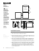
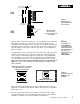
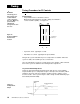
Installation Figure 1 Series 365 Multiple Panel Cutout Dimensions 1.77" to 1.79" (44.96mm to 45.47mm) Panel Cutout Your Panel Thickness çWARNING: The Series 365 Temperature Limit Switch should be mounted in an inconspicuous location to discourage unauthorized changes to the set point. Only approved and appropriate personnel should have the authority to change the set point on the limit switch.
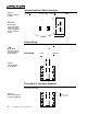
0 to 0.019 space (0 to 0.483 mm) Installation Panel 3A Ridges Bezel Tabs Figure 3 Mounting, Case Side View & Collar Cross Section Mounting Collar External Case Gasket Teeth 3B Mounting Collar Cross Section (notice the offset teeth on each tab) Now let’s make sure we have a tight seal. Use your thumb to lock the tabs into place while pressing the case from side to side. Don’t be afraid to apply enough pressure to install the control.
Power/Switches Internal Heat/Cool Switch Location Figure 5 Heat/Cool Switch Settings k 3 6 5 A - _ _ _ _ - _ 0 0 0 and 365B-____-_000 k Heat/Cool Switch NOTE: Removing the Series 365 chassis from its case will make changing the Heat/Cool switch easier. Heat Mode (switch toward the back of the control) Cool Mode (switch toward the front of the control) Bottom View Power Wiring l 100/120VAC 365_-____-1000 NOTE: The line voltage is determined by your model number.
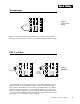
Input Wiring Thermocouple + 3 - 5 Figure 8 Thermocouple Wiring T/C When an external device with a non-isolated circuit common is connected to the DC (open collector) output, you must use an isolated or ungrounded thermocouple. RTD, 2 or 3 Wire S1 2 S1 2 S2 3 S2 3 S3 5 3 Wire RTD S3 5 Figure 9 RTD Wiring 2 Wire RTD Jumper Terminals #3 and #5. Long lead lengths create electrical resistance.
Output Wiring Solid State Relay, 0.5A With Contact Suppression: 365_-B___-_000 Without Contact Suppression: 365_-K___-_000 Only available on units with ON/OFF or PI control Figure 10 Solid State Relay Wiring L2 External Load 9 N.O. Fuse 1 0 COM L1 Switched DC, Open Collector Non-Isolated 365_-C___-_000 Only available on units with ON/OFF or PI control Figure 11 Switched DC Wiring 9 O.C. + 10 O.C.
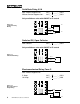
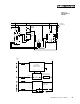
System Example Figure 13 System Wiring Example L1 120 VAC Indicator on when limit trips L2 Earth Ground Coil Fuse 21 High Limit Mechanical Contactor 22 11 1 2 (+) 11 12 SSR-240-10G-DC1 1 3 (-) Out 2 DC Input SSR 3 1 4 3 (+) In Heater 5 (-) 9 (+) Red 1 0 (-) Red 8 N.C. 9 Com 10 N.O.
Tuning k Tuning Procedure for PI Controls NOTE: The tuning procedure must be performed with the control chassis in the case. Make any potentiometer adjustments through the slots in the case. 365B - XXXX-X0XX Initial Settings: • Proportional band: 5 to 50°F/2.8 to 27.8°C Maximum proportional band is clockwise (CW), the minimum is counter clockwise (CCW). See Figure 14. k Figure 14 Proportional Band Potentiometer Location Proportional Band Potentiometer Top View • Cycle time, fixed.
T/C Calibration The Series 365 is calibrated and tested before leaving the factory. Thermocouple Calibration 365X-X6XX-X000 Equipment required: • Precision millivolt source (mV source). • Appropriate type reference compensator with reference junction at 32°F/0°C. Setup: 1. Wire your control for the correct line voltage. See power wiring on Page 6, Figure 6. 2.
RTD Calibration The Series 365 is calibrated and tested before leaving the factory. RTD Calibration 365X-X1XX-X000 Equipment required: • 1KΩ Decade Box Setup: 1. Wire your control for the correct line voltage. See power wiring on Page 6, Figure 6. 2. Connect the decade box to the S1 and S2 terminals on the Series 365 (Terminals 2 and 3). See Page 7, Figure 9. 3. Make sure the heat/cool switch is in the correct position for your application. See Page 6, Figure 5. Apply power. 4.
Troubleshooting Problem Probable Cause Action Poor temperature control. The proportional band is not adjusted properly. Adjust the proportional band per Tuning. See Page 10. The load will not turn ON. 1. An open sensor. Repair or replace. 2. The load circuit is open. Check the fuses, circuit breakers, load, and wiring. See Output Wiring, Page 8. 3. The AC input is not connected or is connected improperly. Check the AC input connections. If not present or proper, connect per Power Wiring.
Glossary Automatic Reset (Integral) - Used in proportional control systems to automatically pick up any system droop. This action may be adjustable or fixed, and adjusts the output level to obtain agreement between actual process temperature and controller set point. Automatic Reset on Power Loss - The limit control does not recognize the power outage as a limit condition. When power is restored, the output will energize automatically as long as a temperature limit condition does not exist.
General Returns 1. Call Watlow Customer Service, 507/454-5300, for a Return Material Authorization (RMA) number before returning any item for repair. We need this information: • • • • • Ship-to address • Bill-to address Contact name • Phone number Ship via • P.O. number Symptoms and/or special instructions Name and phone number of person returning the material 2. Prior approval and an RMA number is needed when returning any unused product for credit.
Watlow Series 365 User’s Manual Watlow Controls, 1241 Bundy Blvd., P.O.