
Manual

WATLOW Series 365 User’s Manual 5
Installation
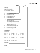
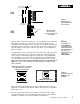
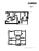
0 to 0.019 space
(0 to 0.483 mm)
Bezel
Panel
External
Case Gasket
Mounting Collar
Ridges
Teeth
Tabs
Figure 3 -
Mounting, Case
Side View & Collar
Cross Section
3A
3B
Mounting Collar
Cross Section
(notice the offset teeth
on each tab)
NOTE:
To guarantee a
proper NEMA 4X
seal, make sure the
gasket between the
panel and the rim of
the case is not
twisted and is seat-
ed properly.
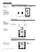
PRESS FIRMLY.
Now let’s make sure we have a tight seal. Use your thumb to lock the tabs into
place while pressing the case from side to side. Don’t be afraid to apply
enough pressure to install the control. The tabs on each side of the collar have
teeth which latch into the ridges. See Figure 3B. Each tooth is staggered at a
different height, so only one of the tabs on each side are ever locked into the
ridges at any time.
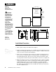
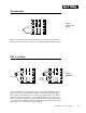
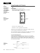
Looking at Figure 4, you see that the tabs on one side of the collar correspond
with those on the opposite side. Make sure that the two corresponding tabs
are the only ones locked in the ridges at the same time. If the matching tabs
are not holding the case at the same time you will not have a NEMA 4X seal.
You can make a visual check, or use your finger nail to pull out on each tab.
Only one on each side is engaged, and they must be corresponding as in
Figure 4. The space between the bezel and panel must be between 0 and
0.019” (0.48mm).
When removing the mounting collar, we suggest sliding a thin tool such as a
putty knife or screwdriver under all three tabs on each side at once and pulling
it back off the case.
5. Insert the control chassis into its case and press the bezel to seat it. Make
sure the inside gasket is also seated properly and not twisted. The hardware
installation is complete. Proceed to the wiring section from here.
NEMA 4X Seal Example.
Make sure that the two correspond-
ing tabs below are locked in the
ridges at the same time.
Figure 4 -
Case Rear View and
NEMA 4X Seal
Example