
Manual

6 WATLOW Series 365 User’s Manual
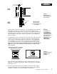
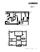
Power/Switches
Fuse
L1
L2
11
12
N.O.
Momentary
Reset Switch
6
7
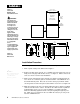
Figure 6 -
120 and 240VAC
Power Wiring
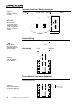
Figure 5 -
Heat/Cool Switch
Settings
Power Wiring
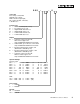
100/120VAC 3 6 5 _ - _ _ _ _ - 1 0 0 0
and
208/240VAC 3 6 5 _ - _ _ _ _ - 2 0 0 0
Reset Switch, Customer Supplied
Limit versions only
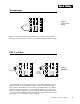
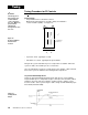
Internal Heat/Cool Switch Location
3 6 5 A - _ _ _ _ - _ 0 0 0 and 3 6 5 B - _ _ _ _ - _ 0 0 0
NOTE:
The line voltage is
determined by your
model number.
NOTE:
Removing the
Series 365 chassis
from its case will
make changing the
Heat/Cool switch
easier.
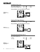
Figure 7 -
Reset Switch Wiring
(Customer Supplied)
Bottom View
Heat/Cool
Switch
Heat Mode
(switch toward
the back of
the control)
Cool Mode
(switch toward
the front of
the control)