
Manual

WATLOW Series 365 User’s Manual 7
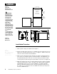
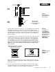
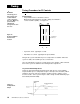
Input Wiring
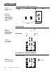
Thermocouple
RTD, 2 or 3 Wire
Figure 8 -
Thermocouple
Wiring
Figure 9 -
RTD Wiring
T/C
+
-
3
5
S1
S2
S3
2
3
5
3 Wire RTD
S1
S2
S3
2
3
5
2 Wire RTD
Jumper
Terminals
#3 and #5.
When an external device with a non-isolated circuit common is connected to the
DC (open collector) output, you must use an isolated or ungrounded thermocouple.
Long lead lengths create electrical resistance. There will be approximately + 2°F
input error for every 1Ω of lead length resistance, when using a two wire RTD.
That resistance, when added to the resistance of the RTD element, can result in
erroneous input to the instrument. To overcome this problem, use a three wire
RTD sensor, which compensates for lead length resistance. When extension wire
is used for a three wire RTD, all three extension wires must have the same electri-
cal resistance. (i.e. same gauge, copper stranded)