
Manual

WATLOW Series 365 User’s Manual 9
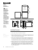
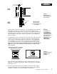
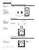
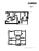
System Example
Figure 13 -
System Wiring
Example
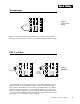
988A-10CA-AARR
Rear View
(+)
10
9
22
21
12
13
(-)
L1
L2
(-)
120 VAC
Fuse
365D-D601-1000
Limit Control
Heater
Process Sensor
Limit Sensor
Red
High Limit
Mechanical
Contactor
Earth Ground
(+)
DC Input
SSR
SSR-240-10G-DC1
In
Out
1
2
4
3
Coil
11
(+)
5
3
12
11
9
10
(-)
N.O.
Red
Com
8
Indicator on
when limit trips
N.C.
1
120VAC
L1
L2
2
9
10
4
5
1 2
1
2
(+)
(-)
3
12
17
13
14
2
1CR
15
Hi Temp. Light
1
2
3
4
8
9
10
11
R
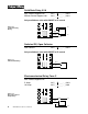
SSR-240-10G-DC1
DC Input Solid State Relay
16
1
9
Heater
Out
24-240VAC
(+)
(-)
3-32VDC
In
1 CR-1
10 11
2
12 13
78
21 22
5
6
7
Limit Control
Series 988
988A-10CA-AARR
Temperature control
Series 365
365D-D601-1000
9
10
8
5
11 12
3
(+)
(-)
11
6