
Instruction Manual


0600-0028-0007 Rev D (2393) Made in the U.S.A.
January 2011
Mounting and Installation
Instructions
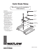
Solid State Relay
PROCEDURE:
1. Surface must be flat and clean.
2. Use thermal pad or a thin coat
of Dow DC-340 thermal joint
compound between the relay
and heatsink.
3. Mount to heatsink or suitable
aluminum or copper plate.
4. Use Belleville (spring) washers
and tighten alternately until
spring is slightly deflected.
(approximately 6 inch pounds).
5. Heatsink should be mounted so
that fins are vertical.
6. Ambient temperature not to
exceed 122°F / 50°C when
mounted to suitable heatsink.
7. Do not mount SSR's on panels
that are painted, plastic, steel,
or stainless steel. These materi-
als will not remove the heat
generated by the SSR.
8. Torque 6-32 screws for signal
wires to 10 in-lbs.
9.Torque screws for power con-
nections to 20 in-lbs.
See the reverse side for typical
SSR wiring diagrams.
1241 Bundy Blvd., P.O. Box 5580, Winona, MN 55987-5580
Phone: 507-454-5300, Fax: 507-452-4507 www.watlow.com
Screw #8-32
99-1017
Washer
Belleville #8
99-3047
Solid State
Relay
Thermal Pad
0830-0574-0000
Typical
Heatsink
A
ir
F
lo
w