
Owner`s manual

Watson Industries, Inc. GGC-E101 Rev A 08/30/2013
17
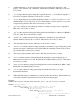
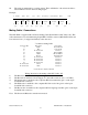
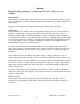
10. The string is terminated by a carriage return. There will then be a short interval with no
data transmission before the next string begins.
Example:
G
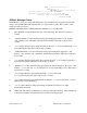
161409.9 -000.8 +00.1 273.4 +028.9 4451.84413,N 09128.00182,W 00894 <CR>
↑
↑ ↑ ↑ ↑ ↑ ↑
↑ ↑
(1)
UTC
(2)
Bank
angle
(3)
Elev.
angle
(4)
Head.
angle
(5)
Velocity
(6)
Latitude
(7)
Longitude
(8)
Altitude
(9)
(10)
space space space space space space space space space
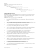
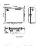
Mating Cable / Connections
The GGS-E101 is supplied with a 65 meter mating Cable (Part Number: GGC Cable –65). This
cable terminated at one end with mating 10 pin MIL-C-26482 connector (MS3116F12-10S) and
four inch wire lead (1” stripped and tinned) at the other end.
Wiring direction for the mating cable GGC Cable –65)
1) The Black wire is attached to the power supply Ground.
2) The Red wire is attached to Power Supply V+ (unit will work from +18 to +35 VDC).
3) The Orange wire is attached to the computers RS-232 transmit line (pin 3 on the 9-pin
D-sub RS-232 connector).
4) The White wire is attached to the computers RS-232 receive line (pin 2 on the 9-pin
D-sub RS-232 connector).
5) The Brown wire is attached to the computers RS-232 signal ground line (pin 5 on the 9-pin
D-sub RS-232 connector).
Note: The Green and Blue wires remain unconnected.
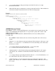
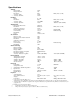
7 conductor mating Cable
Connector Pin Wire Color Description
A Black Power Ground
B Red V+ Power In
C No Connection Not Used
D Orange RS-232 RXD
E White RS-232 TXD**
F Brown Signal Ground
G No Connection Not Used
H No Connection Not Used
J No Connection Not Used
K No Connection Not Used
No Connection Green Not Used
No Connection Blue Not Used
**User Receives data from this line