WATSON-MARLOW BREDEL MANUALS m-520dun-4x-gb-05 Watson-Marlow 520DuN IP66/NEMA 4X pumps Contents 1 2 3 4 5 6 7 8 9 10 11 12 13 14 15 16 17 18 Declaration of conformity 3 Declaration of incorporation 3 Five-year warranty 4 When you unpack your pump 5 Information for returning pumps 6 Peristaltic pumps: an overview 7 Safety notes 8 Pump specifications 10 8.1 Dimensions 15 Good pump installation practice 16 9.1 General recommendations 16 9.
9 520R, 520R2 and 520RE installation 29.1 Opening the guard 29.2 520R and 520R2 tube loading 29.3 520RE: fitting the drain port 29.4 520RE Element loading 29.
1 Declaration of conformity This declaration was issued for Watson-Marlow 720DuN pumps on May 1, 2007. When this pump unit is used as a stand-alone pump it complies with: Machinery Directive 98/37/EC, Low Voltage Directive 73/23/EC, EMC Directive 89/336/EC. This pump is ETL listed: ETL control number 3050250. Cert to CAN/CSA std C22.2 No 61010-1. Conforms to UL std 61010A-1. See 8 Pump specifications.
3 Five year warranty 520 cased pumps, 620 cased pumps and 720 cased pumps For any 520, 620 or 720 cased pump purchased after 1 January 2007, WatsonMarlow Limited (“Watson-Marlow”) warrants, subject to the conditions and exceptions below, through either Watson-Marlow, its subsidiaries, or its authorised distributors, to repair or replace free of charge, any part of the product which fails within five years of the day of manufacture of the product.
4 When you unpack your pump Unpack all parts carefully, retaining the packaging until you are sure all components are present and in good order. Check against the components supplied lists, below. Packaging disposal Dispose of packaging materials safely, and in accordance with regulations in your area. Pay particular attention to the expanded polystyrene shockproof shells. The outer carton is made of corrugated cardboard and can be recycled. Inspection Check that all components are present.
Storage This product has an extended shelf life. However, care should be taken after storage to ensure that all parts function correctly. Users should be aware that the pump contains a battery with an unused life of seven years. Long-term storage is not recommended for peristaltic pump tubing. Please observe the storage recommendations and use-by dates which apply to tubing you may wish to bring into service after storage.
6 Peristaltic pumps - an overview Peristaltic pumps are the simplest possible pump, with no valves, seals or glands to clog or corrode. The fluid contacts only the bore of a tube, eliminating the risk of the pump contaminating the fluid, or the fluid contaminating the pump. Peristaltic pumps can operate dry without risk. How they work A compressible tube is squeezed between a roller and a track on an arc of a circle, creating a seal at the point of contact.
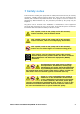
7 Safety notes In the interests of safety, this pump and the tubing selected should only be used by competent, suitably trained personnel after they have read and understood this manual, and considered any hazard involved. If the pump is used in a manner not specified by Watson-Marlow Ltd, the protection provided by the pump may be impaired. Any person who is involved in the installation or maintenance of this equipment should be fully competent to carry out the work.
There are moving parts inside the pumphead. Before opening the toolunlockable pumphead guard, ensure that the following safety directions are followed. Ensure that the pump is isolated from the mains power. Ensure that there is no pressure in the pipeline. If a tube failure has occurred, ensure that any fluid in the pumphead has been allowed to drain to a suitable vessel, container or drain. Ensure that protective clothing and eye protection are worn if hazardous fluids are pumped.
8 Pump specifications Labels fixed to the rear of the pump contain manufacturer and contact details, product reference number, serial number and model details. The same information is carried on the drive’s backplate, accessible when the 520N module is removed.
520DuN, IP66 NEMA 4X model This pump can be controlled from the keypad or remotely. It features: Manual control Speed adjustment; run and stop; direction control; keypad scaling; “max” key for rapid priming. Remote control The pump can be digitally controlled with a contact closure or logic input signal to operate the pump. Analogue control The pump speed can be controlled through an analogue signal input in the ranges 0-10V or 4-20mA. Scaling can be controlled similarly using Analogue signal input 2.
IP (Ingress Protection) and NEMA definitions IP NEMA 1st Digit 3 Protected against ingress of solid objects with a diameter of more than 2.5mm. Tools, wires etc with a thickness of more than 2.5mm are prevented from approach 5 Protected against harmful dust deposits. Ingress of dust is not totally prevented but the dust must not enter in sufficient quantity to interfere with satisfactory operation of the equipment. Complete protection against contact 6 Protection against ingress of dust (dusttight).
Pump specifications Control range (turndown ratio) Supply voltage/frequency Maximum voltage fluctuation Installation category (overvoltage category) Power consumption Full load current Eprom version Enclosure rating Pumphead options Operating temperature range Storage temperature range Maximum altitude Humidity (non-condensing) Pollution degree 0.1-360rpm (3,600:1) 100-120V/200-240V 50/60Hz 1ph ±10% of nominal voltage.
Standards Safety of machinery—electrical equipment of machines: BS EN 60204-1 Safety requirements for electrical equipment for measurement, control and laboratory use: BS EN 61010-1 incorporating A2 Category 2, Pollution degree 2 Degrees of protection provided by enclosures (IP code): BS EN 60529 amendments 1 and 2 Conducted emissions: BS EN 55011 A1 and A2 Class A, called by BS EN61000-6-4 Radiated emissions: BS EN 55011 A1 and A2 Class A, called by BS EN61000-6-4 Electrostatic discharge: BS EN 61000-4-2 A
8.1 Dimensions 520DuN IP66/NEMA 4X model Unit weights IP66 NEMA 4X Drive only + 520R, 520R2 + 520REL, 520REM, 520REH + 505L 10.58kg 23lb 5oz 11.48kg 25lb 5oz 11.40kg 25lb 2oz 13.
9 Good pump installation practice 9.1 General recommendations A correctly engineered installation will promote long tube life. Site the pump on a flat, horizontal, rigid surface, free from excessive vibration, to ensure correct lubrication of the gearbox. Allow a free flow of air around the pump to ensure that heat can be dissipated. Ensure that the ambient temperature around the pump does not exceed 40C. The STOP key on the keypad will always stop the pump.
Do not strap the control and mains power cables together. Do keep delivery and suction tubes as short and direct as possible - though ideally not shorter than 1m - and follow the straightest route. Use bends of large radius: at least four times the tubing diameter. Ensure that connecting pipework and fittings are suitably rated to handle the predicted pipeline pressure. Avoid pipe reducers and lengths of smaller bore tubing than the pumphead section, particularly in pipelines on the suction side.
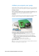
10 Connecting this product to a power supply The voltage selector is mounted in the switchplate at the rear of the pump, protected from water by the 520N module. The module must be removed to allow access to the switchplate. See 22.1 520N module fitting. Set the voltage selector to 115V for 100-120V 50/60Hz supplies or 230V for 200-240V 50/60Hz supplies. Always check the voltage selector switch before connecting the mains supply. Make suitable connection to an earthed single-phase mains electricity supply.
If the mains power cable is inappropriate for your installation, it can be changed. This operation can be carried out with the 520N module in place, or after it has been removed, as shown here for clarity. Ensure that the pump is isolated from the mains power. Remove the six screws from the interface card cover underneath the pump. Lift off the interface card cover. You may find it convenient to remove the cover completely; if so, remove the cover earth lead.
Input line fusing: type T2,5A H 250V 20mm time-delayed fuse, located in a fuseholder in the centre of the switchplate at the rear of the pump. Power interruption: This pump has an auto-restart feature which, when active, will restore the pump to the operating state it was in when power was lost. See 18.12 Auto-restart. Stop / start power cycles: Do not power up/power down for more than 100 starts per hour, whether manually or by means of the auto-restart facility.
11 Start-up check list Note: See also 29.2 Tube loading. Ensure that proper connections are achieved between the pump tube and suction and discharge piping. Ensure proper connection has been made to a suitable power supply. Ensure that the recommendations in the section on 9 Good pump installation practice are followed. 12 Switching the pump on for the first time Note: This manual uses bold type to highlight the active option in menu screens: “English” in the first screen represented here.
First-time start-up defaults Language Not set Analogue input 4-20mA Speed Maximum User trim None Direction Clockwise Remote stop Open=run Pumphead 520R Pump number 1 Tube size 9.6mm Baud rate 9600 Calibration from head and tube table Stop bits 2 Backlight On Xon/Xoff Off Keypad lock Off Scrolling increment 0.
13 Switching the pump on in subsequent power cycles (if not in auto-restart mode) Switch on the power supply at the rear of the pump. The pump runs a poweron test to confirm proper functioning of the memory and hardware. If a fault is found, an error message is displayed. See 25.1 Error codes. The pump displays the Watson-Marlow start-up screen for four seconds followed by the pump model identity screen for four seconds, and then the manual mode main screen.
14 Manual operation 14.1 Keypad functions in manual mode All settings and functions of the pump in manual mode are set and controlled by means of key-presses. Immediately after the start-up display sequence detailed above, the manual mode main screen will be displayed. The currently selected rotation direction is indicated on the display by a clockwise or counter-clockwise segmented arrow. If an exclamation mark ( ! ) shows, it indicates that Auto-restart is on (see 18.12 Auto-restart).
MAX: while pressed, MAX operates the pump at the maximum allowed speed and in the direction shown on the display. When released, the pump returns to its previous status. Note: Priming can be achieved by pressing the MAX key until fluid flows through the pump and reaches the point of discharge, and then releasing the MAX key. AUTO/MAN: displays a screen offering three choices: manual control, ana- logue control or network (RS485) control. Use the UP and DOWN keys to make a choice.
ENTER: cycles the information shown on the manual mode main screen from revolutions per minute, to flowrate in a choice of units (via a warning screen if flowrate has not been calibrated) to rpm, flowrate and Run time. (See START, above. See 17 Calibrate. See 18.9 Run time.) This cycle operates when the pump is stopped and when it is running. The default can be altered from within the Setup menu. See 18.3 Display.
14.2 Keypad lock The keypad can be locked to prevent changes to pump speed or other settings, and make it possible only to start or stop the pump. The padlock symbol shows on the display. While the pump is running, hold down the START key for two seconds. The padlock symbol shows and only the START and STOP keys function. The keypad may also be locked while the pump is stopped. Hold down the STOP key for two seconds. The padlock symbol shows and only the START and STOP keys function.
15 Main menu 15.1 Keypad functions in menu screens In addition to their functions in other operations, the following keys have specific actions in menu screens: STOP: In general, STOP functions as a “go back” key, taking the user up one menu level without making a change. UP: The UP key is used in menu item selection: it moves a highlight up the menu. When a numerical entry screen is displayed, pressing UP increases the number displayed.
15.2 Main menu entry The MENU key displays the main menu. It operates at any point in the pump’s activity except where error screens are displayed, or screens where UP and DOWN keys are used to enter values. The main menu offers five options: Calibrate, Setup, Pin out details, MemoDose and Exit. Use the UP and DOWN keys to make a choice. Press the ENTER key to confirm your decision.
16 PIN-secure process protection E SS C PROC TION P S E CUR E IN PROT E The 520DuN and 520Du feature PIN-secure process protection. This allows the pump to be configured to suit the application, and for the setup to be protected by two levels of PIN code. See 18.19 Security code setup.
17 Calibrate The pump can display flowrate in a choice of units as well as speed in revolutions per minute. It must first be calibrated. Pump calibration can be limited to users who correctly enter a three-digit security code. If a security code has been set, selecting Change from the calibration details screen and confirming with the ENTER key causes the pump to display the Security code entry sequence. See 16 PIN-secure process protection.
Head and tube If Head and tube is selected, the pump displays a list of standard pumpheads that can be fitted to the pump. It occupies two screens. Use the UP and DOWN keys to move the highlight down the list. When the last item on the first screen is highlighted, a further press on the DOWN key causes the pump to display the second screen with its first item highlighted. Use the UP and DOWN keys to make a selection. Press ENTER to confirm. An example is shown here.
Calibration dose The pump offers to run a calibration dose. Use the UP and DOWN keys to choose Yes or No. Press ENTER to confirm. Examples are shown here. If No is selected after a tube selection has been made (see Tube above), the pump briefly displays a confirmation screen showing current head, tube and flow settings, and redisplays the main menu.
Measure the quantity of fluid dispensed. The pump displays its calculated dose, based on previous calibration data. Use the UP and DOWN keys to adjust this reading to match the measured volume. Press ENTER. The pump displays the new head, tube and flow settings, and redisplays the main menu. Example figures are shown here. Note: If the pump has been set to display flow rate in units of mass (see 18.
18 Setup Entry to the Setup menu can be limited to users who correctly enter a three-digit security code. If a security code has been set, selecting Setup and confirming with the ENTER key causes the pump to display the Security code entry sequence. See 16 Security code entry. If no security code has been set, the pump displays the first of six screens containing the Setup menu. The Setup menu The Setup menu occupies six screens. The first two are shown here.
18.1 Trim When the pump is under remote control, it tracks an analogue signal from the user’s remote control system to the i/p terminal of the Analogue 1 and Analogue 2 connectors at the rear of the pump within the ranges 4-20mA or 0-10V. The Trim setup sequence allows the user to customise the process-signal-to-pump-speed calibration. The sequence may be entered directly from the Setup menu or from the Analogue setup menu.
The final press on ENTER ends the Analogue 1 trimming sequence. If Analogue 2 has been configured, the pump displays a similar sequence of screens for that input. Apply the low, high and mid-range signal to the i/p terminal of the Analogue 2 connector as instructed in the display, pressing ENTER each time to record the signals as calibration points. If a mistake is made, press STOP at any point in the sequence, and the pump displays the previous screen.
Input 1 - speed allows the user to tell the pump which signal type he will apply to Analogue 1, or to choose the program option. If he selects Program from the subsequent menu, the user can choose his input type and tell the pump the speeds at which to operate on receiving a low or high process control signal. See Input speed.
Program Select Program using the UP or DOWN keys and press ENTER to confirm. The pump offers two choices: mA and V. Use the UP or DOWN keys to make a selection and press ENTER to confirm your decision. The pump displays a screen allowing you to set the speed for low signal input. Use the UP and DOWN keys to scroll the display to your chosen speed and press ENTER to confirm the figure. The pump displays a screen allowing you to set the speed for high signal input.
Scaling - stroke Select Scaling - stroke using the UP or DOWN keys and press ENTER to confirm your choice. The pump offers five further choices: Off, Keypad, 4-20mA, 0-10V and Program. Use the UP or DOWN keys to make a selection and press ENTER to confirm your decision. If Off is selected, scaling control is disabled and the pump displays the Analogue setup menu. The other options allow a choice of inputs to control scaling.
18.3 Display The pump can display three default screens in manual mode: revolutions per minute, flowrate in a choice of units, or both. In the first screen of the Setup menu select Display using the UP and DOWN keys. Press ENTER to confirm your choice. The pump displays a screen allowing you to choose the format of the manual mode main screen. Use the UP and DOWN keys to choose and press ENTER to confirm your decision.
18.4 Pump number The 520DuN pump can be individually controlled under RS485 as one of up to 32 pumps. First it must be given its identity number. In the first screen of the Setup menu select Pump no 1 using the UP and DOWN keys. Press ENTER to confirm your choice. The pump displays a screen allowing you to change the pump’s identity number. Use the UP and DOWN keys to change the number in the display to an integer from 1 to 32 and press ENTER to confirm your decision. An example is shown here.
18.6 Stop bits The 520DuN pump can be set to communicate with control devices at a choice of stop bits settings. In the second screen of the Setup menu select Stop bits using the UP and DOWN keys. Press ENTER to confirm your choice. The pump displays a screen allowing you to change the pump’s stop bits setting. Use the UP and DOWN keys to select 2, 1, or 0 and press ENTER to confirm your decision. The pump displays the second screen of the Setup menu. 18.
18.8 Flow units The 520DuN pump can display its flow rate in metric (SI) or US (imperial) units of volume or mass. In the second screen of the Setup menu select Flow units using the UP and DOWN keys. Press ENTER to confirm your choice. The pump displays a screen offering Metric or US. Use the UP and DOWN keys to choose and press ENTER to confirm your decision. If you chose Metric, the pump offers a choice of units: µl/min, ml/min, l/hr, g/min or kg/hr.
If you chose a volumetric flow rate from either screen, a confirmation screen appears briefly and the pump displays the second screen of the Setup menu. If you chose a mass flow rate from either screen, the pump asks for the specific gravity of the fluid to be pumped. Use the UP and DOWN keys to enter a value between 0.01 and 15.00. Press ENTER to confirm your decision. Press STOP if you decide to make a different choice of units.
18.10 Outputs The 520DuN pump offers four relay status outputs. See 12 Switching the pump on for the first time for initial startup defaults. Each of five parameters can be configured to any output, or more than one output. The parameters are: Run / stop Provides a status output to indicate whether the pumphead is in a running or stopped condition. When running at 0rpm, the run / stop output indicates running. Direction Provides a status output to indicate which direction the pump is set to run in.
In the third screen of the Setup menu select Outputs using the UP and DOWN keys. Press ENTER to confirm your choice. The pump displays a screen allowing you to configure each of the four outputs, or to exit this menu. Use the UP and DOWN keys to choose and press ENTER to confirm your decision. If Output 1 is chosen, the pump displays the five options.
18.11 Remote stop The 520DuN pump can be started and stopped with a remote switch between the 5V terminal and the i/p terminal of the Run/stop input, using an open=run or open=stop command sense. It also operates with a logic input between 5V and 24V on the i/p terminal of the Run/stop input. Disabling the remote stop control does not disable other remote controls. In the third screen of the Setup menu select Remote stop using the UP and DOWN keys. Press ENTER to confirm your choice.
If Yes is chosen, the pump asks the user whether the remote stop feature is to be disabled fully (for both manual and auto operation), or only for manual operation, leaving remote stop functioning when the pump is operating in auto mode. Choose using the UP and DOWN keys and press ENTER to confirm. If manual and auto was chosen, the pump briefly displays a confirmation screen (an example is shown here) and returns the user to the third screen of the Setup menu.
18.12 Auto-restart This pump offers an auto-restart feature. If active on power loss, it restores the pump when power returns to the operating state it was in when power was lost. It does not operate when powering down in the middle of a dose: when the pump is restarted, it will await a press on the START key to begin the interrupted dose again. Auto-restart is retained while the pump is switched off. When the pump starts running, look for the ! symbol on the display.
18.13 Set maximum speed The 520DuN pump offers a maximum speed of 220 revolutions per minute. This limit can be reduced for operational purposes. In the fourth screen of the Setup menu select Set max speed using the UP and DOWN keys. Press ENTER to confirm your choice. The pump displays a screen allowing the user to set the maximum speed of the pump equal to or lower then the maximum available. Use the UP and DOWN keys to set the maximum allowed speed and press ENTER to confirm the figure.
18.15 ROM The pump can display its software version, model number and pump speed. In the fourth screen of the Setup menu select ROM using the UP and DOWN keys. Press ENTER to confirm your choice. The pump displays the software version, model number and pump speed for four seconds, then returns the user to the fourth screen of the Setup menu. It also displays a checksum: CHK 123, for example. This may be required if reporting pump performance to the Watson-Marlow service department. Alternatively ...
18.17 Defaults All the pump’s user-set data can be reset to factory defaults. In the fifth screen of the Setup menu select Defaults using the UP and DOWN keys. Press ENTER to confirm your choice. A warning is displayed for four seconds, and the pump asks the user to confirm that factory defaults are to be reset.
18.19 Security code Access to the pumpís Setup menu, direction control and keypad lock can be restricted to those who correctly enter a three-digit security code: the main code. A secondary user code can be set, which permits PIN access to direction and keypad lock, but blocks access to Setup. See 18 Setup, 14.1 Keypad functions in manual mode and 14.2 Keypad lock. The code must first be set. In the fifth screen of the Setup menu select Security code using the UP and DOWN keys. Press ENTER to confirm.
If you chose Cancel codes, any codes previously set are cancelled and access to the pump is not restricted. If you chose Set main code or Set user code, the pump displays a screen with three blank spaces for digits and the instruction “Enter new code”. Use the UP and DOWN keys to enter three digits. Press ENTER to confirm each one. The pump displays a similar three-digit entry screen and the instruction “Confirm code”. Repeat the digit-entry sequence.
20 MemoDose Each time the pump is started by pressing START, it records the number of pumphead revolutions which occur until STOP is pressed. The number of revolutions is proportional to the volume of fluid which has been dispensed: the dose. The MemoDose facility allows the user to repeat-dose a precise volume of fluid. To do so, a quantity of fluid must be dispensed as the master dose which the MemoDose facility can repeat exactly or proportionately.
To repeat the dose The pump has recorded the number of pumphead revolutions required to dispense the master dose. If the volume of fluid in the measuring vessel is the volume required, press START to repeat the dose. If the volume of fluid in the measuring vessel differs from the volume required, the percentage may be adjusted within the limits 1% to 999% of the master dose. Use the UP or DOWN keys to alter the percentage. Press START to dispense the new dose.
Press the STOP key twice within half a second to return to MemoDose. The display shows the previous percentage dose size. The pump will dose at the new speed. Note: To retain the MemoDose value through a power interruption the pump must be in auto-restart mode. The dosing cycle will resume at the start of a dose and wait for START to be pressed, with the MemoDose percentage screen displayed. See 18.12 Auto-restart. 20.
22 Automatic control wiring Interfacing the pump with other devices is by means of screw-terminal connectors within the 520N watertight module at the rear of the pump. Suitable cable must be passed into the module through one or more watertight cable glands and connected appropriately. The module must be removed to allow this. It is important to check the pump’s voltage setting to ensure that it matches the supply. The voltage selection switch is on the rear panel of the drive.
If necessary, unplug the two 25-way D-connectors linking the module to the pump drive. If necessary, remove the module’s earth link from the back of the drive. However, the link is long enough to allow the module to fold back to give access to the the circuit board inside and to the back of the drive. To replace the 520N watertight module: Check that the fuse in the fuseholder (ringed) in the centre of the switchplate does not need to be replaced.
22.2 Wiring up It is the user’s responsibility to ensure the pump’s safe and reliable operation under remote and automatic control. The 0V lines on this pump are commoned and mains transformer-isolated from ground (floating ground). It can be connected to isolated 0V or grounded 0V interfaces. Cable entry to the module is via up to four watertight cable glands. These may be fitted in place of the sealing plugs which are fitted to the back of the module when the pump is shipped.
Suitable cables for general-purpose use: 300V with extra premium grade PVC jacket with good flame and moisture resistance. Suitable cables for industrial use: 300V extra-rugged polyurethane grade jacket with resistance to oils, fuels, solvents and water. For convenience of wiring more than 8 conductors per cable may be awkward to handle. Only two appear in the illustrations here, for clarity. Use a 19mm spanner to unscrew the sealing plug. Discard the nylon sealing washer.
Strip the outer sheath as necessary and remove 5mm of insulation from the conductors. No tinning or ferrule is required. Note: If very stiff or large-diameter cable is used, it may be convenient to strip the outer sheath before passing the cable’s conductors through the gland. However, to ensure a seal, cable with an undamaged sheath must be present within the gland when it is tightened. Twist a suitable length of the cable screen. Loosen one of the pcb retaining screws and wind the shielding round it.
22.3 Speed: analogue input It is possible to control the speed of the pump remotely by one of these methods: a voltage analogue signal within the range 0-10V; or a current analogue signal within the range 4-20mA; or a remote potentiometer using the 10V supply at J7. The analogue process signal must be applied to the i/p terminal of the Analogue 1 connector (J5). Ground to the 0V terminal of the same connector.
22.4 Scaling: analogue input It is possible to scale the speed of the pump remotely by one of these methods: a voltage analogue signal within the range 0-10V; or a current analogue signal within the range 4-20mA; or a remote potentiometer using the 10V supply at J7. The analogue process signal must be applied to the i/p terminal of the Analogue 2 connector (J8). Ground to the 0V terminal of the same connector. 4-20mA circuit impedance: 250Ω.
22.5 Speed: analogue output An analogue voltage output signal is available on the Tacho output connector (J11), between the V terminal and the 0V terminal. The voltage is fixed and directly proportional to the pumphead rotation speed. 0V = zero speed; 10V = maximum allowed speed. A current analogue signal within the range 4-20mA is available between the mA terminal and the 0V terminal. The current is fixed and directly proportional to the pumphead rotation speed. 4mA = zero speed; 20mA = maximum speed.
Important: general instructions for remote control inputs All remote control inputs can be wired in two ways: Logic A logic voltage between 5V TTL and 24V industrial logic may be wired to the input. The pump is configured to operate without modification anywhere in this range. Any of the 0V terminals - though preferably the 0V terminal associated with the desired input - is connected to the control device’s 0V to make the circuit. Low is equivalent to 0V. High is equivalent to 5V 24V.
22.9 Auto / manual toggle input Connect a remote switch between the +5V terminal and the i/p terminal of the Auto-man i/p connector (J1). Closed switch for automatic control; open switch for manual control. Alternatively a logic input may be applied to the i/p terminal of the Auto-man i/p connector, ground to the 0V terminal. High input for automatic control; low input for manual control. 22.
Important: pump status outputs Outputs 1-4 are available as single-pole change-over relay contacts: Relay 1, 2, 3 and 4. Connect to the normally open or normally closed contacts of the relay as required and configure the pump’s software accordingly. See 18.10 Outputs. Note: The maximum rating on the relay contacts of this pump is 30V DC; maximum load 30W. Note: Also suitable for low power: ie, 1mA at 5VDC minimum. 22.12 Outputs 1, 2, 3, 4 Note: Relay 1 (J14) is represented here.
DC Voltage Max load Typical use 10mA Voltage supply for inputs using remote switch. Possible voltage supply for outputs if only 5V is required. +12V 10mA Possible voltage supply for inputs using remote switch. Possible voltage supply for outputs. Voltage supply for Watson-Marlow Tube Monitor leak detector. Part voltage supply (-12V also needed) for the Watson-Marlow proximity switch. -12V 10mA Part voltage supply (+12V also needed) for the Watson-Marlow proximity switch.
23 Automatic control and operation Check that the pump is ready to run before selecting automatic operation. Remote control signals may start the pump without warning. How to get into auto operation While the maunal mode main screen is displayed, press the AUTO/MAN key, or apply a high signal (5V to 24V) to the remote auto / manual input. If auto entry was triggered remotely, the pump responds to the analogue signal as soon as this is done and shows the “AUTO” icon.
The pump is automatically switched into auto-restart mode and displays the ! icon. The only keys active are STOP, AUTO/MAN, DIRECTION and START (available only as an extended keypress to toggle keypad lock). UP and DOWN keys are available if manual scaling has been set (see below). If the remote direction input is active and the direction-enable link is applied, the DIRECTION key is disabled.
Emergency stop In an emergency press the STOP key. The pump stops and displays an interruption screen. If keypad lock is in place when STOP is pressed, or if the pump is in auto mode via the digital input, the interruption screen offers one key-press: press START to continue auto operation. If keypad lock was not in place when STOP was pressed, the interruption screen offers a choice: Continue to continue auto operation, or Manual to switch to manual mode.
24 Network control and operation Check that the pump is ready to run before selecting network operation. Remote control signals may start the pump without warning. How to get into network operation While the maunal mode main screen is displayed, press the AUTO/MAN key. The pump offers three choices: Analogue, Manual and Network. Use the UP and DOWN keys to choose and press ENTER to confirm. Selecting Manual returns the user to the manual mode main screen. See 14 Manual operation.
How to get out of network operation Pressing the AUTO/MAN key displays three options: Analogue, Manual and Network. Use the UP and DOWN keys to choose and press ENTER to confirm. Selecting Manual sets the pump to manual operation and retains the set speed and run status from its previous operation in network mode. See 14 Manual operation. Selecting Network returns the pump to network (RS485) mode. Selecting Analogue sets the pump to analogue mode. See 23 Automatic control and operation.
24.1 RS485 command strings Command Parameters Meaning nCA - Clear LCD display nCH - Home the cursor nDO xxxxxxxxxx<,yyyyy> Set and run one dose of xxxxxxxxxx tacho pulses, with optional drip of yyyyy (maximum 11,000) tacho pulses. See note 1 nTC - Clear the cumulative tachometer count nSP xxx.x Set speed to xxx.
25 Troubleshooting If the pump display remains blank when the pump is on, make the following checks: Check the position of the voltage selector switch. The voltage selector is mounted in the switchplate at the rear of the pump, protected from water by the 520N module. The module must be removed to allow access to the switchplate. See 22.1 520N module removal and replacement. Check the mains power switch at the rear of the pump. Check that mains power is available to the pump.
25.1 Error codes If an internal error occurs, a flashing error screen is displayed. Note: Signal out of range, Over signal, No signal and Leak detected error screens report the nature of an external signal. They do not flash. Error condition Suggested action RAM write error Attempt to reset by switching power OFF / ON. Or seek support RAM corruption Attempt to reset by switching power OFF / ON.
26 Drive maintenance There are no user serviceable parts inside the pump (except the power cable: see 10 Connecting this product to a power supply). The unit should be returned to Watson-Marlow or its appointed agents or distributors for service.
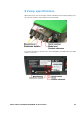
28 The 520R, 520R2 and 520RE pumpheads Identification of parts 520R/520R2 1 Guard latch 2 520REL/520REM/520REH 5 Rotor cap 9 Pumping roller Guard (520R, 520R2) 6 Tube guide roller 10 Tube clamp slider (520R, 520R2) 3 Track 7 Rotor 11 Tube clamp (520R, 520R2) 4 Clutch button cover 8 Follower roller 12 Guard with seal (520RE) 13 Drain port (520RE) Watson-Marlow 520DuN IP66/NEMA 4X User Manual 80
28.1 Pumphead position, removal and replacement Always isolate the pump from the mains power supply before opening the guard or performing any positioning, removal or maintenance activity. The pumphead track can be fitted in one of three orientations to provide right, up or down input/output port positions, whichever is convenient. Position the pumphead so that the tube ports face up or down only where the drive is placed on the bench edge - otherwise the pump tube or the hinged guard will impact the bench.
Rotor removal Remove any tubing from the pumphead. Open the flexible rotor cap in the centre of the rotor. Undo and withdraw the central locating screw using a slotted screwdriver. Pull the rotor hub off its dogged shaft. Between the hub and the shaft is a split collet. If the collet is retained by the shaft, pull it off, loosening it if necessary by tapping it lightly. Avoid levering it off using a screwdriver or other tool.
29 520R, 520R2 and 520RE installation Always isolate the pump from the mains power supply before opening the guard or performing any positioning, removal or maintenance activity. 29.1 Opening the pumphead guard Unlock the pumphead guard by turning the guard fastener 1⁄4 turn anticlockwise with a slotted screwdriver. Open the guard to its full extent to create maximum clearance for the tube ports. Ensure that the rollers rotate freely and that the tube clamps are clean.
29.2 520R and 520R2 tube loading 520R continuous tubing pumpheads are factory-set to accept Watson-Marlow 1.6mm-wall tubing. 520R2 continuous tubing pumpheads are factory set to accept Watson-Marlow 2.4mm-wall tubing. Pumping performance may be adversely affected if Watson-Marlow tubing is not used. Mark a 225mm (8 7⁄8 in) length onto the section of the tubing which is to be located into the pumphead.
The spring-loaded tube clamps must grip the tubing tightly enough to stop it moving in and out of the pumphead but must not over-squeeze the tube and throttle fluid flow. The tubing clamps are fitted with yellow sliders which can be clicked into two positions while the clamps are held open: the outer position will allow the clamps to grip the tube tightly; the inner will grip the tube loosely. Adjust the sliders to prevent tube movement during a few trial rotations of the rotor.
29.4 520RE Element loading 520RE tubing element pumpheads are factory-set to accept Watson-Marlow 2.4mmwall tubing elements. Elements fitted with either quick-release industrial connectors or Tri-clamp sanitary connectors may be used; however, it is vital to match the pressure rating of the element with the pressure rating of the pumphead so that the correct roller-spring rate and occlusion settings are used. The pressure rating of the pumphead appears on the flexible rotor cap in the centre of the rotor.
Check that the conical connector sleeve of the element to be fitted is the same colour as the pumphead rotor cap 520RE element loading procedure Note: The element loading procedure is the same for industrial (pictured) and sanitary elements. Select an appropriate Watson-Marlow 520RE tubing element, paying attention to pressure capability, bore size, tubing material and type of connector. See the table above for pressure ratings.
29.5 520RE Element connection Select suitable tubing to connect to the tubing element supply and discharge connectors. Check that its pressure rating is appropriate to the application. Sanitary 3⁄4in mini-Tri-clamp connectors Sanitary connectors are connected to a tubing system using mini-Tri-clamps and gaskets. Hold the connector end of the supply or discharge tube against the element connector, with a gasket between them. Use a Tri-clamp to engage both flanges squarely, close it and tighten.
30 520R, 520R2 and 520RE maintenance Always isolate the pump from the mains power supply before opening the guard or performing any positioning, removal or maintenance activity. As part of regular cleaning and maintenance (and at least every three months), lubricate the pivot points, the follower rollers and the tube guide rollers with Ultra Lube (PA 1240), which is a non-toxic perfluoroether-based grease.
General guide to cleaning with solvents Chemical Cleaning precautions Aliphatic hydrocarbons Remove guard. Minimize rotor cap and clutch boot exposure to less than one minute (risk of attack). Re-lubricate follower and tube guide rollers. Aromatic hydrocarbons Remove guard. Minimize rotor cap and clutch boot exposure to less than one minute (risk of attack). Re-lubricate follower and tube guide rollers. Ketone solvents Remove guard.
32 Pumphead spares 520R/520R2 520REL/520REM/520REH 053.1011.100 520R 053.1011.2L0 520R2 053.1011.EL0 520REL 053.1011.EM0 520REM 053.1011.EH0 520REH 1 MNA2050A (520R, 520R2) Pumphead guard complete with tool-unlockable latch 2 MNA2045A (520R, 520R2) Track assembly for cased pumps complete with springloaded tube clamps 3 MNA2076A MNA2077A MNA2148A MNA2149A MNA2150A Rotor cover, rotor cap and clutch button (520R - 1.6mm wall tube) (520R2 - 2.
33 Flow rates Pumping conditions For precise and repeatable performance it is important to determine flow rates under operating conditions for each new piece of tubing. When rotating counter-clockwise, 520R, 520R2 and 520RE pumpheads’ flow rates are directly proportional to rotor speed. When rotating clockwise, 520R, 520R2 and 520RE pumpheads’ flow rates are directly proportional to rotor speed up to 1.5 bar; their performance above 1.5 bar should be determined empirically.
520RE Performance figures for the 520REL and 520REM have been recorded against 2bar peak pressure and 4bar peak pressure respectively. Performance figures for the 520REH have been recorded against 7bar constant pressure. Although the 520REL is rated to 2bar (30psi) peak pressure, the 520REM is rated to 4bar (60psi) peak pressure and the 520REH is rated to 7bar (100psi) constant pressure, the pumps will generate in excess of these pressures if the system pressures exceed this.
Continuous tubing 520R Neoprene, Sta-Pure, Chem-Sure, PVC, Pumpsil (ml/min) Speed 0.5mm 0.8mm 1.6mm 3.2mm 4.8mm 6.4mm range 8.0mm 9.6mm 1.12400 1.63500 8.0mm 9.6mm 1.12300 1.53300 520DuN/R, 520DuN/R2 0.10.004220rpm 9.5 0.0124 0.0497 0.18390 0.40870 0.701500 520R Marprene / Bioprene 64 shore tubing (ml/min) Speed 0.5mm 0.8mm 1.6mm 3.2mm 4.8mm 6.4mm range 520DuN/R, 520DuN/R2 0.10.004220rpm 9.0 0.0123 0.0492 0.17370 0.38830 0.671500 520R Fluorel (ml/min) Speed range 1.6mm 3.2mm 4.
Elements 520REL Neoprene, Sta-Pure, Chem-Sure, Pumpsil (ml/min) Speed range 3.2mm 520DuN/REL 0.10.18220rpm 390 6.4mm 9.6mm 3.2mm 6.4mm 9.6mm 0.701500 1.63500 0.17370 0.671500 1.53300 520REL Neoprene, Sta-Pure, Chem-Sure, Pumpsil (USGPH) Speed range 3.2mm 520DuN/REL 0.10.003220rpm 6.1 520REL Marprene / Bioprene TL (ml/min) 520REL Marprene / Bioprene TL (USGPH) 6.4mm 9.6mm 3.2mm 6.4mm 9.6mm 0.0125 0.0355 0.0035.9 0.0123 0.
Performance curves Marprene continuous tubing, 1.6mm wall, 200rpm, clockwise rotation Marprene continuous tubing, 1.
Marprene continuous tubing, 2.4mm wall, 200rpm, clockwise rotation Marprene continuous tubing, 2.
Marprene TL element, 0-2 bar (0-30psi), 200rpm, counter-clockwise rotation Sta-Pure element, 0-2 bar (0-30psi), 200rpm, counter-clockwise rotation Marprene TM element, 2-4 bar (30-60psi), 200rpm, counter-clockwise rotation Sta-Pure element, 2-4 bar (30-60psi), 200rpm, counter-clockwise rotation Watson-Marlow 520DuN IP66/NEMA 4X User Manual 98
Marprene TH element, 4-7 bar (60-100psi), 200rpm, counter-clockwise rotation Watson-Marlow 520DuN IP66/NEMA 4X User Manual 99
34 Tubing and element part numbers 1.6mm wall tubing for 520R pumpheads mm inch # Marprene Bioprene /50 112 902.0005.016 903.0005.016 /32 13 902.0008.016 903.0008.016 /16 14 902.0016.016 903.0016.016 965.0016.L16 /8 16 902.0032.016 903.0032.016 965.0032.L16 /16 25 902.0048.016 903.0048.016 965.0048.L16 /4 17 902.0064.016 903.0064.016 965.0064.L16 /16 18 902.0080.016 903.0080.016 965.0080.L16 inch # PVC Fluorel Neoprene /32 13 /16 14 950.0016.016 970.0016.
2.4mm wall tubing for 520R2 pumpheads mm inch 0.5 1 0.8 1 1.6 1 3.2 4.8 6.4 8.0 9.6 mm 913.A008.024 /16 119 902.0016.024 903.0016.024 913.A016.024 /8 120 902.0032.024 903.0032.024 913.A032.024 /16 15 902.0048.024 903.0048.024 913.A048.024 /4 24 902.0064.024 903.0064.024 913.A064.024 /16 121 902.0080.024 903.0080.024 913.A080.024 /8 122 902.0096.024 903.0096.024 913.A096.024 inch # Chem-Sure Sta-Pure /16 119 965.0016.024 960.0016.024 1 3 1 5 3 1.6 8.
2.4mm wall elements for 520RE pumpheads 0-2 bar (0-30 psi) pressure rated elements Industrial mm inch # Marprene TL /8 16 902.0032.PFQ 913.A032.PFQ 920.0032.PFQ 965.0032.PFQ /4 17 902.0064.PFQ 913.A064.PFQ 920.0064.PFQ 965.0064.PFQ 3.2 1 6.4 1 9.6 3 /8 Pumpsil Neoprene Chem-Sure 122 902.0096.PFQ 913.A096.PFQ 920.0096.PFQ 965.0096.PFQ Sanitary mm inch # Bioprene TL /8 16 903.0032.PFT 913.A032.PFT 960.0032.PFT 965.0032.PFT /4 17 903.0064.PFT 913.A064.PFT 960.0064.PFT 965.0064.
35 520 series pumping accessories Accessory 520ANC 520ANX 520ANA 520AB Description Network cable, RS232, with 9-pin D-connectors Network extension cable with 9-pin D-connectors Network adaptor, 25-pin to 9-pin D-connectors Batch records cable with 9-pin D-connectors Part code 059.3121.000 059.3122.000 Pump compatibility 520Du, 520Di 520Du, 520Di 059.3123.000 059.3125.000 520Di 520AF Footswitch with 25-pin D-connector 059.3002.000 520AH Handswitch with 25-pin D-connector 059.3022.
36 Trademarks Watson-Marlow, Bioprene, Pumpsil, LoadSure and Marprene are trademarks of Watson-Marlow Limited. Fluorel is a trademark of 3M. Sta-Pure and Chem-Sure are trademarks of W.L.Gore and Associates. 37 Warning not to use pumps in patient-connected applications Warning These products are not designed for use in, and should not be used for patient-connected applications. 38 Publication history m-520dun-4x-gb-05.qxp: Watson-Marlow 520DuN IP66 NEMA 4X First published 12 03. Revised 09 06.
39 Decontamination certificate In compliance with the UK Health and Safety at Work Act and the Control of Substances Hazardous to Health Regulations, you are required to declare the substances which have been in contact with product(s) you return to Watson-Marlow or its subsidiaries or distributors. Failure to do so will cause delays. Please ensure that you fax us this form and receive an RGA (Returned Goods Authorisation) before you despatch the product(s).