
Water Pump User Manual


Watson-Marlow 520DuN IP66/NEMA 4X User Manual 70
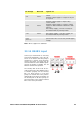
DC Voltage Max load Typical use
+5V 10mA
Voltage supply for inputs using remote
switch.
Possible voltage supply for outputs if only 5V
is required.
+12V 10mA
Possible voltage supply for inputs using
remote switch.
Possible voltage supply for outputs. Voltage
supply for Watson-Marlow Tube Monitor leak
detector.
Part voltage supply (-12V also needed) for
the Watson-Marlow proximity switch.
-12V 10mA
Part voltage supply (+12V also needed) for
the Watson-Marlow proximity switch.
+10V
(from J7)
Reference voltage for remote potentiometer
speed control. Do not use as a general supply
voltage.
Note: All DC supplies are stabilised.
22.14 RS485 input
Connect your network link to J10 using
a screened twisted pair: A to A, B to B,
screen to 0V. Ensure that the pump is
configured to operate under Network
control. More than one pump may be
controlled with the same RS485 signal:
connect all pumps in parallel. See 24
Network control and operation.
The shorting link at J20 must be cor-
rectly positioned to allow RS485 control
to function properly. Fit the shorting
link of a single pump or of the last
pump on a network line in the position
marked INT on the three-pin header; fit
the shorting link of all other pumps on
the network line in the position marked
EXT on the three-pin header.