
User's Manual


2
There are three configurations of the sensor:
• The FSP-321B mounts inside the fixture.
• The FSP-321B-S mounts to a fixture or an enclosure with a 1/2”
knockout.
• The FSP-321B-D mounts to a pole or fixture.
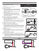
Mounting Inside the Fixture
1. Determine an appropriate mounting location inside the light fixture
minimizing the electric light contribution to the sensor’s photocell.
Allow a minimum distance of 0.2” (5.1mm) from the wiring end of
the sensor to the wall of the fixture.
2. Drill a hole 1.30” (33.0mm) in diameter through the sheet metal in
the bottom of the fixture.
3. Add the rubber gasket to the threaded collar, and install the
sensor face down, parallel to the mounting surface. Ensure the
rubber gasket touches the inside surface of the fixture. Install
the skirt securely against the fixture to a torque of 25-30 in-lbs to
ensure IP rating is maintained.
Mounting to a Fixture/Enclosure – Straight Nipple
1. Determine an appropriate mounting location minimizing the
electric light contribution to the sensor’s photocell.
2. If there is no knockout, drill a hole 0.875” (22mm) in diameter through the sheet
metal in the fixture or enclosure.
3. Add the rubber gasket to the nipple, and install the sensor face down. Ensure the
rubber gasket touches the surface of the fixture. Install the nipple nut securely
against the fixture to a torque of 25-30 in-lbs to ensure IP rating is maintained.
Mounting to a Pole or Fixture – Drop Nipple
1. Determine an appropriate mounting location on the pole.
2. Drill a hole 0.875” (22mm) in diameter through the pole.
3. Add the rubber gasket to the nipple, and install the sensor face down. Ensure the
rubber gasket touches the surface of the fixture. If needed, add the nut between
the sensor body and the rubber gasket to ensure a secure fit. Install the nipple
nut securely against the fixture to a torque of 25-30 in-lbs to ensure IP rating is
maintained.
Completing the Installation
1. Align the locking features between the sensor and lens module and push the lens
module forward until the o-ring seals firmly. Turn the lens module clockwise to
ensure it locks in place.
2. Connect wires as shown in wiring diagram.
3. Restore power from the circuit breaker.
NOTE: The IP66 rating for this unit is based on proper installation as indicated above.
However, as Fixture housings may vary in thickness, material, and hole dimensions
to accommodate this unit, all precautions to maintain IP66 should be be considered
with the combination and installation of the unit to the Fixture Housing. This includes
installation to an IP66 rated Fixture Housing and use of suitable outdoor rated
silicone seals or accessories.
WIRING
Non-Dimming
Load
Load
(Red)
Gray
Violet
Neutral or
Phase B
White with
Black Stripe
s
Neutral or
Phase B
Black Line or
Phase A
Dimming
Load
Neutral or
Phase B
White with
Black Stripe
s
Load
(Red)
Neutral or
Phase B
Black Line or
Phase A
Dim (-)
Gray
Dim (+)
Violet
Skirt
Fixture
Wall
Lens Assembly
Outside
Fixture Wall
Inside Fixture
Wall
Mounting Within Fixture
Rubber
Gasket
Rubber
Gasket
Skirt
12
NOTE: The Outside Fixture Wall thickness should be no
greater than 0.125” (3.18mm) for optimal sensor
mounting and security.
INSTALLATION
WARNING
TURN THE POWER OFF AT THE CIRCUIT BREAKER
BEFORE INSTALLING THE SENSOR.
Straight Nipple Mount
Nipple
Rubber
Gaskets
Nipple
Nut
Drop Nipple Mount
Nipple
Nut
Nipple
Rubber
Gaskets
Drop Nipple Mount
Nipple
Rubber
Gaskets
Nipple
Nut
Nut