
User's Manual

WALL-MOUNT POWER SUPPLY INSTALLATION
The MRDP10 can be insta l led in a user occupied space within radio ra n g e
of the wire l e s s network dev i ces. It must be insta l led in acco rd a n ce with
national and lo cal ele c t r i cal codes by qualified pers o n n e l .
The MRDP10 housing is designed for installation in a 3-gang ele c t r i c al box
using four mounting holes on the unit. Radio co m m u n i cation cannot be
g u a ra n teed if the unit is mounted in a metallic ele c t r i cal enclo s u re.
1 . C o m p le te the physical installation and binding of all other wire le s s
d ev i c es in the network.
2 . Shut off the circuit bre a k e r.
3 . I n s tall a 3-gang (minimum) ele c t r i cal wall box in a lo cation co n ve n i e n t
to the system user.
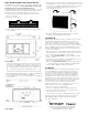
Back of MRDP10
4 . W i re the MRDP10 to the 120VAC supply circuit using the NEUTRAL and
LINE terminals as indica ted on the back of the MRDP10.
5 . S e c u re the MRDP10 to the ele c t r i c al wall box using the 4 mounting hole
s c rew lo c a t i o n s .
Front of MRDP10
Do not lo c a te the MRDP10 close to any dev i ce that may ca u s e
i n t e r fe re n c e or behind large metal objects that can block ra d i o
re ception. Avoid flu o r e s cent light fix t u r es, TV sets, co m p u te rs ,
re f r i g e ra to rs, microw a ve ovens, range hoods, safes, etc .
CAUTION
TURN THE POWER OFF AT THE CIRCUIT
BREAKER BEFORE INSTALLING THE MRDP10.
2800 De La Cruz Bouleva rd, Santa Clara, CA 95050
Te c h n i cal Support: 800.879.8585 • 972.578.1699
w w w. w a t t s to p p e r. c om
05988r1 09/2005
FCC NOTICE
This equipment has been te s ted and found to co m p ly with the limits
for a Class B digital dev i c e, pursuant to part 15 of the FCC Rule s .
These limits are designed to provide re a s o n a b le pro t ection against
harmful inte r fe re n c e in a residential installation. This equipment
g e n e ra tes, uses and can ra d i a te radio frequency energy and, if not
i n sta l l ed and used in acco rd a n c e with the instructions, may ca u s e
harmful inte r fe re n c e to radio co m m u n i c ations. However, there is no
g u a ra n tee that inte r fe re n c e will not occur in a particular insta l l a t i o n .
If this equipment does cause harmful inte r fe re n ce to radio or
te levision re c eption, which can be determined by turning the
equipment off and on, the user is enco u r aged to try to co r rect the
i n t e r fe re n c e by one or more of the fo l lowing measure s :
• Reorient or re lo ca t e the re c eiving ante n n a .
• I n c rease the separation between the equipment and re ce i ve r.
• Connect the equipment into an outlet on a circuit diffe r ent fro m
that to which the re ce i ver is co n n e c te d .
• Consult the dealer or an ex p e r i e n ced radio/TV technician for help.
Caution: Any changes or modifications to this dev i ce not ex p l i c i t ly
a p p r oved by Watt Sto p p e r / L e g rand could void your authority to
o p e ra te this equipment.
6 . Hang the To u c h s c reen from the To u c h s c r een Hanger Arms on the fro n t
of the MRDP10. Once yo u ’ re sure that the hanger arms are in all 4 slo t s
of the To u c h s c reen, lightly push dow n w a rd on the To u c h s c r een frame to
e n s u r e that the Low Vo l t age Contacts make connection to the
To u c h s c r een battery co n t a c t s .
7 . The status LED lights ye l l ow, indicating that the unit is ready fo r
co n fi g u r ation. See SET HOUSE ID in this manual.
SET HOUSE ID
All Watt Stopper Top Dog wire l e ss dev i ces insta l led in the same syste m
m u st acquire the same unique House ID befo re use. This pro ce s s is
k n own as house binding. Each wire l e ss dev i c e is bound to all other
w i r e le ss dev i ces in the house. If you are not familiar with the binding
p r o c e ss for the dev i c es in your installation, please rev i ew the Insta l l a t i o n
Guide, or individual installation instructions provided with the dev i ce s .
The House ID binding gives the To u c h s c r een the same House ID as the
re st of the wire le s s network.
1 . M a k e sure all dev i ces are insta l l ed and energized and all group, house,
and room bindings are co m p le t e. Make sure that every other wire le s s
d ev i ce LED is green and the MRDS10 is ye l low (amber).
2 . P re s s on any p rev i o u s ly bound d ev i ce until its LED flashes amber
(about 2 seco n d s ) .
3 . Verify that the LED on the MRDS10 starts flashing green. This sets the
House ID to match the other dev i c es in the house.
4 . Return to the same prev i o u s ly bound d ev i ce used in step 2 and pre s s
until its LED changes to solid green (about 2 seconds). All dev i ce
LEDs including the MRDS10 should now be solid gre e n .