
Specifications


SERVICE INSTRUCTIONS
board. Move the spring clip loop to the right and hold. Rotate the
motor at least a 1/4 turn in either direction before gently pulling
on the wire connectors to remove the motor. Pulling directly on
the wires without rotating the motor may break the wires off the
motor.
Replace the motor if necessary. Do not lubricate the motor or the
gears. When reinstalling the motor gently turn the motor while
inserting so that the gear on the motor meshes with the gears
under the drive gear cover and the small plastic bulge engages
one of the slots on the motor housing. Reconnect the motor plug
to the two-pronged jack on the lower left-hand side of the PC
board. If motor will not easily engage with drive gear when rein-
stalling, lift and slightly rotate motor before reinserting.
Replace the valve cover. After completing any valve mainte-
nance, press and hold NEXT and REGEN buttons for 3 seconds
or unplug power source jack (black wire) and plug back in. This
resets the electronics and establishes the service piston position.
The display should flash all wording, then flash the software ver-
sion (e.g. 154) and then reset the valve to the service position
.
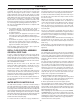
DRIVE CAP ASSEMBLY, MAIN PISTON
AND REGENERANT PISTON
The drive assembly must be removed to access the drive cap
assembly. The drive cap assembly must be removed to access
the piston(s). The drive cap assembly is threaded into the con-
trol valve body and seals with an o-ring. To remove the drive cap
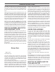
assembly, use the special plastic wrench or insert a 1/4" to 1" flat
bladed screwdriver into one of the slots around the top 2" of the
drive cap assembly so it engages the notches molded into the
drive back plate around the top 2" of the piston cavity. See
Figure 5. The notches are visible through the holes. Lever the
screwdriver so the drive cap assembly turns counter clockwise.
Once loosened unscrew the drive cap assembly by hand and
pull straight out.
The drive cap assembly contains the drive cap, the main drive
gear, drive cap spline, piston rod and various other parts that
should not be dissembled in the field. The only replaceable part
on the drive cap assembly is the o-ring. Attached to the drive cap
assembly is the main piston (downflow or upflow) and if a regen-
erant is used, a regenerant piston.
The regenerant piston (the small diameter one behind the main
piston) is removed from the main piston by unsnapping it from
its latch. Chemically clean in dilute sodium bisulfite or vinegar or
replace the regenerant piston if needed. To remove the main-
downflow or upflow piston fully extend the piston rod and then
unsnap the main piston from its latch by pressing on the side
with the number. Chemically clean in dilute sodium bisulfite or
vinegar or replace the main piston.
Reattach the main piston to the drive cap assembly. Reattach
the regenerant piston (if needed) to the main piston. Do not
lubricate the piston rod, main piston or regenerant piston.
Lubricant will adversely affect the red or clear lip seals. Reinsert
the drive cap assembly and piston into the spacer stack
assembly and hand tighten the drive cap assembly. Continue to
tighten the drive cap assembly using a screwdriver as a ratchet
until the black oring on the spacer stack assembly is no longer
visible through the drain port. Excessive force can break the
notches molded into the drive back plate. Make certain that the
main drive gear still turns freely. The exact position of the piston
is not important as long as the main drive gear turns freely.
Reattach the drive assembly to the control valve and connect all
plugs. After completing any valve maintenance, press and hold
NEXT and REGEN buttons for 3 seconds or unplug power
source jack (black wire) and plug back in. This resets the elec-
tronics and establishes the service piston position. The display
should flash all wording, then flash the software version (e.g.
154) and then reset the valve to the service position.
SPACER STACK ASSEMBLY
To access the spacer stack assembly remove the drive
assembly, drive cap assembly and piston. The spacer stack
assembly can be removed easily without tools by using thumb
and forefinger. Inspect the black o-rings and red or clear lip seals
for wear or damage. Replace the entire stack if necessary. The
spacer stack assembly has been 100% tested at the factory to
insure proper orientation of one-way seals. Do not disassemble
the stack.
The spacer stack assembly may be chemically cleaned (dilute
sodium bisulfite or vinegar) or wiped with a soft cloth.
The spacer stack assembly can be pushed in to the control valve
body bore by hand. Since the spacer stack assembly can be
compressed it is easier to use a blunt object (5/8" to 1-1/8" in
diameter) to push the center of the assembly into the control
valve body. The assembly is property seated when at least four
threads are exposed (approximately 5/8"). Do not force the
spacer stack assembly in. The control valve body bore interior
can be lubricated with silicone to allow for easy insertion of the
entire stack. Do not use silicone or any other type of lubricant on
the red or clear lip seals or the piston.
Reattach the drive cap assembly, and piston(s) and the drive
assembly.
After completing any valve maintenance, press and hold NEXT
and REGEN buttons for 3 seconds or unplug power source jack
(black wire) and plug back in. This resets the electronics and
establishes the service piston position. The display should flash
all wording, then flash the software version (e.g. 154) and then
reset the valve to the service position.
INJECTOR CAP, SCREEN, INJECTOR
PLUG AND INJECTOR
Unscrew the injector cap and lift off. Loosen cap with special
plastic wrench or pliers if necessary. Attached to the injector cap
is a screen. Remove the screen and clean if fouled.
16
Figure 21: To
remove drive cap
Missing Photo