
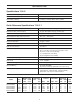
Specifications

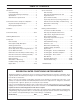

8
INSTALLATION
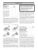
STEP 4: Move brine
tank next to softener
and connect brine
draw line to value.
With brine tank next to the soft-
ener tank connect the brine
drawline to valve body.
Control valves that use a regen-
erant, come equipped with a
3/8" refill flow control assembly.
To complete the regenerant line connections orientate the
outlet in the desired direction and push the plastic insert into
the poly tube. Push the poly tube into the nut. Do not use
pipe dope or other sealant on threads. The threads for the
compression nut do not need Teflon tape. Tighten the nut
securely to create a pressure tight connection. A pliers or
crescent wrench may be used to tighten or unscrew the nut.
The nut, gripper and retainer sleeve is a 3-piece assembly
that can come apart if removed from the elbow body.
Parts
must be reassembled exactly as shown in refill flow con-
trol assembly drawing to function properly. If the nut is
completely removed from the body, slip the nut, plastic
gripper and retainer sleeve on to the tube then tighten on
to the fitting. Complete the connection by installing the
loose end of the tubing to the brine valve in the salt tank.
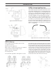
STEP 3:
Move softener
into place
Make sure floor is level.
Install shims if needed.
Measure, cut, and install
pipe and fittings to the
bypass valve (dry fit only
to make sure you have a
proper fit) inlet and out-
let side. Be sure hard
water is supplied to the
inlet side. Trace pipe to
be sure.
The installation fittings connect to the control valve or the
bypass valve using nuts that only require hand tightening.
Hand tighten nut connections between control valve and
installation fittings, control valve and bypass valve, and
bypass valve and installation fittings allow for easy serv-
iceability. Do not use a pipe wrench to tighten nuts on
installation fittings. Hand tighten only.
Split ring retainer design holds the nut on and allows load
to be spread over the entire nut surface area reducing the
chance for leakage. The split ring design, incorporated into
the installation fittings allows approximately 2 degrees off
axis alignment to the plumbing system. The installation fit-
tings are designed to accommodate minor plumbing mis-
alignments but are not designed to support the weight of a
system or the plumbing.
When assembling the installation-fitting package, connect
the fitting to the plumbing system first and then attach the
nut, split ring and o-ring. Heat from soldering or solvent
cements may damage the nut, split ring, or o-ring. Solder
joints should be cool and solvent cements should be set
before installing the nut, split ring, and o-ring. Avoid get-
ting primer and solvent cement on any part of the o-
rings, split rings, and bypass valve or control valve.
Solvent cements and primers should be used in accor-
dance with the manufacturer’s instructions.
Slip the nut onto the fitting first, then the split ring second
and the o-ring last. Hand tighten the nut. If the fitting is
leaking tightening the nut will not stop the leak. Remove
the nut, remove the fitting, and check for damage or mis-
alignment of the o-ring.
Do not use pipe dope or other sealant on threads. Teflon
tapemust be used on the threads of the 1" NPT elbow
and the 1/4" NPT connection and on the threads for the
drain line connection. Teflon tape is not necessary on the
nut connection or caps because of o-ring seals.
Note: When assembling the installation fitting
package, connect the fitting to the plumbing
system first and then attach the nut, split ring
and o-ring. Heat from soldering or solvent
cements may damage the nut, split ring, and
o-ring. Make sure solder joints are cool
before assemble is started.
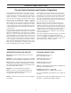
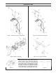
1” PVC MALE NPT ELBOW
1” BRASS SWEAT
Figure 8: Four types of installation fittings.
3/4” BRASS SWEAT
3/4” x1” PVC SOLVENT ELBOW