
Onix Tubing Installation Manual


and will tend to cause an imbalance in
the fluid flow. Some tubing may be
removed from this last circuit as long
as the remaining length is within 10%
of the existing circuits. For example, if
200 ft. lengths were installed, the last
circuit can be cut to a length of 180 ft.
and still maintain a balanced system. If
more than 10% is in excess, run the
remaining tubing along an exposed
wall or in other areas of the zone.
Step 8:
Visual Inspection
After all the circuits are installed, take
a few minutes to walk each circuit and
visually inspect the tubing for possible
damage caused during installation. If
damage is found, repair it using an
approved Watts Radiant Repair Kit.
More information on the repair kits
can be found in the Appendix.
Step 9:
Final Assembly and
Pressure Test
With the zone fully installed and
inspected, finish the connections to the
manifold. Begin by identifying corre-
sponding ends to the same circuit. If
the tubing has not been marked, select
two circuit ends and blow through one,
with a thumb placed over the other
end. Air should be felt on the other
side, confirming both ends of a single
circuit have been selected.
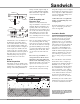
Take one Onix Clamp and slide it over
one end of tubing. Slide the clamp
down about 2" from the end and push
the Onix onto the first barb of the sup-
ply manifold, making sure the tubing
covers the entire fitting. If the Onix is
difficult to push onto the barb, lubri-
cate the end of the Onix with some
water.
Do not use soap, oil, WD-40
®
, or
other petroleum or silicone based
lubricants as they may damage the
interior of the Onix tubing.
Soap and
lubricants may make connections and
splices leak, even at low pressures.
Slide the Onix Clamp back over the
Onix and barb connection. If using
TorqueTite clamps, do not over-tighten
them. Tighten the clamp using a preset
in.-lb. torque driver. More information
on how to install Onix Clamps can be
found in the Appendix.
Caution: DO NOT over tighten the
clamps. Over tightening may cause
an improper fit.
For detailed information on the proper
steps to conducting a pressure test,
refer to the Appendix.
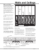
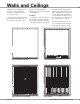
Insulation Details
Foil-faced batt insulation is primarily
used when an air gap can be main-
tained between the tubing and the
insulation. In the case of a Sandwich
application, the air gap is on the sides
of the tubing, not below the tubing. If
the system is to be insulated in the
joist cavity, a standard Kraft faced
insulation can be used. Make sure to
install the insulation tight against the
subfloor to minimize any convective
losses that may be generated.
(note:
this is a change from previous manu-
als.)
The actual R-value of the insulation
should be the same as a Staple Up
™
application. The insulation should be a
minimum of 3-1/2", or R-13, foil-
faced fiberglass batt when the radiant
floor is installed over a heated space,
such as a basement. 5-1/2", or R-19,
foil-faced batts (or thicker, depending
on the climate) should be used when
the area below the radiant floor is
unheated or exposed to the elements.
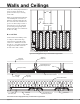
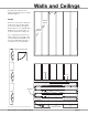
If insulating above the subfloor, then
insulation between the sleepers should
be a foil faced insulation board. We
Watts Radiant: Onix Installation Manual page 29
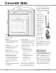
Manifold
Onix Barb
Onix Clamp
Onix
Manifold
Pressure Test Kit
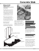
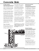
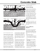
The same techniques are used when installing a
Sandwich application over a slab. The use of an
extruded polystyrene (Dow
®
Blue Board
®
) is rec-
ommended for this application.
Onix Tubing
Insulation Board
Sandwich