
Install Instructions


2
Installation Instructions:
a. Turn off all electrical power to the water heater.
b. Turn off the water supply to the water heater.
c. Drain water from the water heater so that the cold water supply piping is free of water.
d. Close the drain valve after draining water.
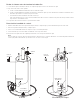
1. Install the Control Unit on the cold water supply piping with the arrow on the valve pointing in the direction of fl ow, towards the
water heater. Figure 1
CAUTION: Do not apply heat directly to the valve body!
Pre-solder the adapter fi ttings that will be used to connect piping to the valve. Use caution when soldering to avoid damage
to the valve cover and internal components.
2. After soldering the piping to the fi ttings, apply thread sealant to the adapter fi ttings and thread the adapters with attached piping
into the valve body. Figure 2
3. Install and solder the piping to the supply and to the inlet of the water heater.
4. Install the Water Detector Pad under the water heater with the green circuit board down. The Water Detector Pad must lie fl at on
the fl oor or in a drain pan. Route the connecting cable to the Control Unit and insert the interlocking connector to the circuit board.
Figure 3
Note: It is not necessary to remove the cover of the Control Unit to install the interconnecting cables. To remove an interlocking cable,
use the supplied Pocket Screwdriver to depress the tab on the cable while pulling cable from its socket. Figure 4
Important: Interconnecting wires must not touch or be in close proximity to any fl ame or hot surface.
a. If no drain pan exists, install the Water Dam around the perimeter of the water heater. The Water Dam can be cut so that it fi ts
approximately 1 to 2 inches outside the diameter of the water heater and includes the area where the Temperature and Pressure
safety relief drain tube terminates.
b. Install the plastic connector supplied with the Water Dam into both ends of the Water Dam so that no gap exists between the
ends. Figure 5 and Figure 5a
5. Install the Power Cutout Module, Figure 6, to the water heater as indicated below.
Oil Fired Water Heater Installation (for Spark Ignition Water Heater Installation, see page 3)
NOTE: Be certain to disconnect the circuit breaker/fuse that supplies power to the oil burner. A warning label should be applied to the
panel with a warning against restoring power while work is in process.
1. Mount the Power Cutout Module Figure 10, as close to the oil burner as possible.
2. Remove the jumper from the TT terminals of the oil burner relay shown in Figure 7.
Figure 1 Figure 2
Figure 3
Figure 4 Figure 5 Figure 5a
Figure 6