
Install Instructions


RP/IS-008QT
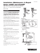
Models: 008
Watts 008QT
3
⁄8",
1
⁄2"
Watts 008QTS
3
⁄4", 1"
Installation, Maintenance, & Repair
Series 008QT and LF008QT
Spill-Resistant Pressure Vacuum Breaker
Sizes:
3
⁄8",
1
⁄2",
3
⁄4" and 1" (10, 15, 20, and 25mm)
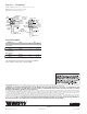
008QT
Min.
of 1"
Watts P60
Pressure Reducing Valve
Solenoid Valve
Shutoffs
Test
Cock
3
⁄4" Hose Adapter
with strainer washer
Dispensing Inducers
Supply Hose
Strainer
Supply Line
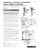
008QT
Flood Rim Level
008QT to be
installed a
minimum of 6"
above the flood
rim if applied for
general plumbing
applications.
6"
Strainer
recommended to
prevent fouling of
the check assembly
and resultant spillage
during start up and
repressurizing.
Installations:
WARNING
!
You are required to thoroughly read all installation instructions
and product safety information before beginning the installa-
tion of this product. FAILURE TO COMPLY WITH PROPER
INSTALLATION AND MAINTENANCE INSTRUCTIONS
COULD RESULT IN PRODUCT FAILURE WHICH CAN
CAUSE PROPERTY DAMAGE, PERSONAL INJURY AND/
OR DEATH. Watts is not responsible for damages resulting
from improper installation and/or maintenance.
Local building or plumbing codes may require modifications to
the information provided. You are required to consult the local
building and plumbing codes prior to installation. If this informa-
tion is not consistent with local building or plumbing codes, the
local codes should be followed.
Need for Periodic Inspection/Maintenance: This product
must be tested periodically in compliance with local codes, but
at least once per year or more as service conditions warrant.
Replace internal components every 5 years.
Corrosive water conditions, and/or unauthorized adjustments
or repair could render the product ineffective for the service in-
tended. Regular checking and cleaning of the product’s internal
components helps assure maximum life and proper product
function.
Installation Requirements
1. Install a minimum of 1" above flood level of fixture if factory
deck mounted or a minimum of 6" if general plumbing
application.
2. Install bonnet side up and allow for accessibility for testing/
service. Do not install in concealed locations or areas where
water leakage can cause damage due to normal wear of the
internal parts.
3. Do not undersize supply or oversize the valve in relation
to demand.
4. Do not install where backpressure can occur.
5. Protect assembly from freezing.
Note: Use “L” suffix for left-hand outlet.
6. The installation of a strainer ahead of the backflow preventer
is recommended to prevent fouling of the check assembly
and resultant spillage from the valve during start up and
repressuring.
Testing
For field testing procedure, send for IS-TK-DL, IS-TK-9A,
IS-TK-99E AND IS-TK-99D.
For other repair kits and service parts, send for PL-RP-BPD.
For technical assistance, contact your local Watts
representative.