
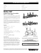
Spec Sheet

As
A
C
B
T
R
D
*Bs
Pressure — Temperature
1
⁄2" – 2" (15 – 50mm)
Temperature Range: 33°F – 180°F (0.5°C – 82°C).
Maximum Working Pressure: 175psi (12.1 bar).
2
1
⁄2" – 3" (65 – 80mm)
Temperature Range: 33˚F – 110°F (0.5˚C – 43°C) continuous,
140°F (60°C) intermittent.
Maximum Working Pressure: 175psi (12.1 bar).
Standards
ASSE Std. 1015, AWWA Std. C510
IAPMO PS31, CSA B64.5
Approvals
† ASSE, AWWA, IAPMO, CSA, UPC
Approved by the Foundation for Cross-Connection Control
and Hydraulic Research at the University of Southern
California.
• Models LF and S are not listed.
UL Classified (LF models only)
3
⁄4" – 2" (20 – 50mm)
(except 009M3LF)
UL Classified with OSY gate valves
(2
1
⁄2" and 3" horizontal only.)
* Horizontal approval on all sizes.
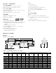
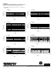
Dimensions – Weights
Models
Sizes:
1
⁄2" – 2" (15 – 50mm)
Suffix:
S - bronze strainer
LF - without shutoff valves
LH - locking handle ball valves (open position)
SH - stainless steel ball valve handles
HC - 2
1
⁄2" inlet/outlet fire hydrant fittings (2" valve)
Prefix:
U - Union connections
2
1
⁄2" – 3" (65 – 80mm)
Suffix:
NRS - non-rising stem resilient seated gate valves
OSY - UL/FM outside stem and yoke resilient seated gate
valves
LF - without shutoff valves
QT-FDA - FDA epoxy coated quarter-turn ball valves
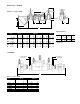
MODEL SIZE (DN) DIMENSIONS WEIGHT
ABCDF G R T
in. mm in. mm in. mm in. mm in. mm in. mm in. mm in. mm in. mm lbs. kgs.
†007QT
1
⁄2 15 10 254 4
5
⁄8 117 2
7
⁄16 62 — — 5 127 3
3
⁄8 85 2
5
⁄16 59 2
1
⁄16 52 4.5 2
†007M3QT
3
⁄4 20 11
1
⁄8 282 4 102 3
1
⁄8 79 — — 6
3
⁄16 157 3
7
⁄16 87 2
1
⁄8 54 1
5
⁄16 33 5 2.3
†007M1QT 1 25 13
1
⁄4 337 5
1
⁄8 130 4 102 — — 7
1
⁄2 191 3
3
⁄8 85 1
11
⁄16 43 1
11
⁄16 43 12 5.4
†007M2QT 1
1
⁄4 32 16
3
⁄8 416 5 127 3
5
⁄16 84 — — 9
1
⁄2 241 5 127 3 76 2 50 15 6.8
†007M2QT 1
1
⁄2 40 16
3
⁄4 425 4
7
⁄8 124 3
1
⁄2 89 — — 9
3
⁄4 248 5
13
⁄16 148 3
1
⁄8 79 2
11
⁄16 68 15.9 7.2
†007M1QT 2 50 19
1
⁄2 495 6
1
⁄4 159 4 102 — — 13
3
⁄8 340 6
1
⁄8 156 3
7
⁄16 87 2
11
⁄16 68 25.7 11.7
• 007QT-S
1
⁄2 15 13 330 6 152 2
7
⁄16 62 3 76 5 127 3
3
⁄8 85 2
5
⁄16 59 2
1
⁄16 52 5.5 2.5
• 007M3QT-S
3
⁄4 20 14
1
⁄2 368 6
1
⁄8 156 3
1
⁄8 79 3 76 6
3
⁄16 157 3
7
⁄16 87 2
1
⁄8 54 1
5
⁄16 33 6.7 3.1
• 007M1QT-S 1 25 17
15
⁄16 157 7
3
⁄4 197 4 102 3
1
⁄4 83 7
1
⁄2 191 3
3
⁄8 85 1
11
⁄16 43 1
11
⁄16 43 14 6.4
• 007M2QT-S 1
1
⁄4 32 21
1
⁄2 546 7
1
⁄16 179 3
5
⁄16 84 3
1
⁄2 83 9
1
⁄2 241 5 127 3 76 2 50 19 8.6
• 007M2QT-S 1
1
⁄2 40 25
1
⁄16 637 7
1
⁄16 179 3
1
⁄2 89 3
3
⁄4 95 9
3
⁄4 248 5
13
⁄16 148 3
1
⁄8 79 2
11
⁄16 68 19.6 8.9
• 007M1QT-S 2 50 27
1
⁄4 692 8
3
⁄4 222 4 102 4 102 13
3
⁄8 340 6
1
⁄8 156 3
7
⁄16 87 2
11
⁄16 68 33.5 15.2
F
*Subscript ‘S’ = strainer model
Suffix HC — Fire Hydrant Fittings dimension “A” = 23
1
⁄2" (594mm)