
User Manual


Installation Instructions
Watts Flow Measurement/Balancing Valves are available in the straightway pattern with threaded or solder end
connections. All tapered pipe threads conform to FEDERAL SPECS H28. Valves conform to ANSI B16.18 and
ANSI B16.22. Maximum Pressure/Temperature Ratings: 300 psi (20.7 bar) - 250°F (121°C).
1. Install valve on return line of equipment to be balanced or as shown on the plans.
2. For maximum accuracy, the flow measurement valve should be located in an unrestricted straight pipe
run so that no fittings (elbow, valve, tee, etc.) is closer to the measurement valve than 5 pipe diameters
upstream and 2 pipe diameter downstream. If a balancing valve is located downstream from a circula-
tion pump, allow a distance of ten (10) diameters between the pump and balancing valves.
3. Series CSM-61M1 and LF-CSM-61M1 flow measurement valves are bi-directional and should be
installed to ensure ease of hooking up meter, adjusting setting, and enabling memory device. A
1
⁄8" (3mm)
NPT plugged port is installed on each measurement valve
1
⁄2" - 1" (15-25mm) and can be used as a drain
port if needed.
4. Solder end valves are designed to be soft soldered into lines without disassembly. Solders such as 95/5
tin antimony 460°F (238°C) can be used, however, extreme caution must be used to prevent seat damage.
Higher temperature solders will damage the seat material.
5. Remove indicator knob prior to soldering. Replace after soldering is completed.
6. Apply heat with flame directed away from the center of the valve body. Excessive heat can harm the seats.
7. Heat solder joints only to the point were solder will flow properly. Excessive heat may distort brass castings.
Flow Measurement Instruction
1. Loosen memory screw.
2. Turn indicator knob to open position on indicator plate. Do not force past this point.
3. Connect, vent and prepare the differential gauge. Refer to instructions furnished with the gauge.
4. After initial pressure differential reading is taken, refer to flow rate charts to obtain flow rate based on
pressure differential and valve setting. If flow rate is in excess of that specified, turn indicator knob towards
closed position, noting pressure drop and valve setting and determining new flow rates from flow rate
chart. Once correct flow rate settings has been established, slide memory screw counter-clockwise
towards closed side of indicator plate until memory stop ring hits indicator plate. Do not force beyond
this point. Tighten memory screw. Refer to Figures 1 and 2. The unit or system has now been balanced
and the memory set.
5. After memory is set, disconnect differential gauge.
Figure 2
Memory
Screw
Series CSM-61M1-T/LF-CSM-61M1-S
Flow Measurement/Balancing Valves
Sizes:
1
⁄2",
3
⁄4", 1"
Figure 1
Memory
Screw
Size Weight
Valve No. (In.) A B (lbs.)
CSM-61T-M1 1 3
1
⁄8
3
⁄4 1.75
LF-CSM-61S-M1 1 3
7
⁄8
3
⁄4 1.87
Note: (T) = Threaded, (S) = Solder
Dimensions (Inches)
Valves conform to ANSI B16.18 and ANSI B16.22
1
7
⁄8
1
7
⁄8
2
A
B
Feet
(Water)*
80.0
40.0
20.0
10.0
5.0
2.0
1.0
.5
Inches
bar
(Water)
960 2.4
480 1.2
240 .6
120 .3
60 .15
24 .06
12 .03
6 .02
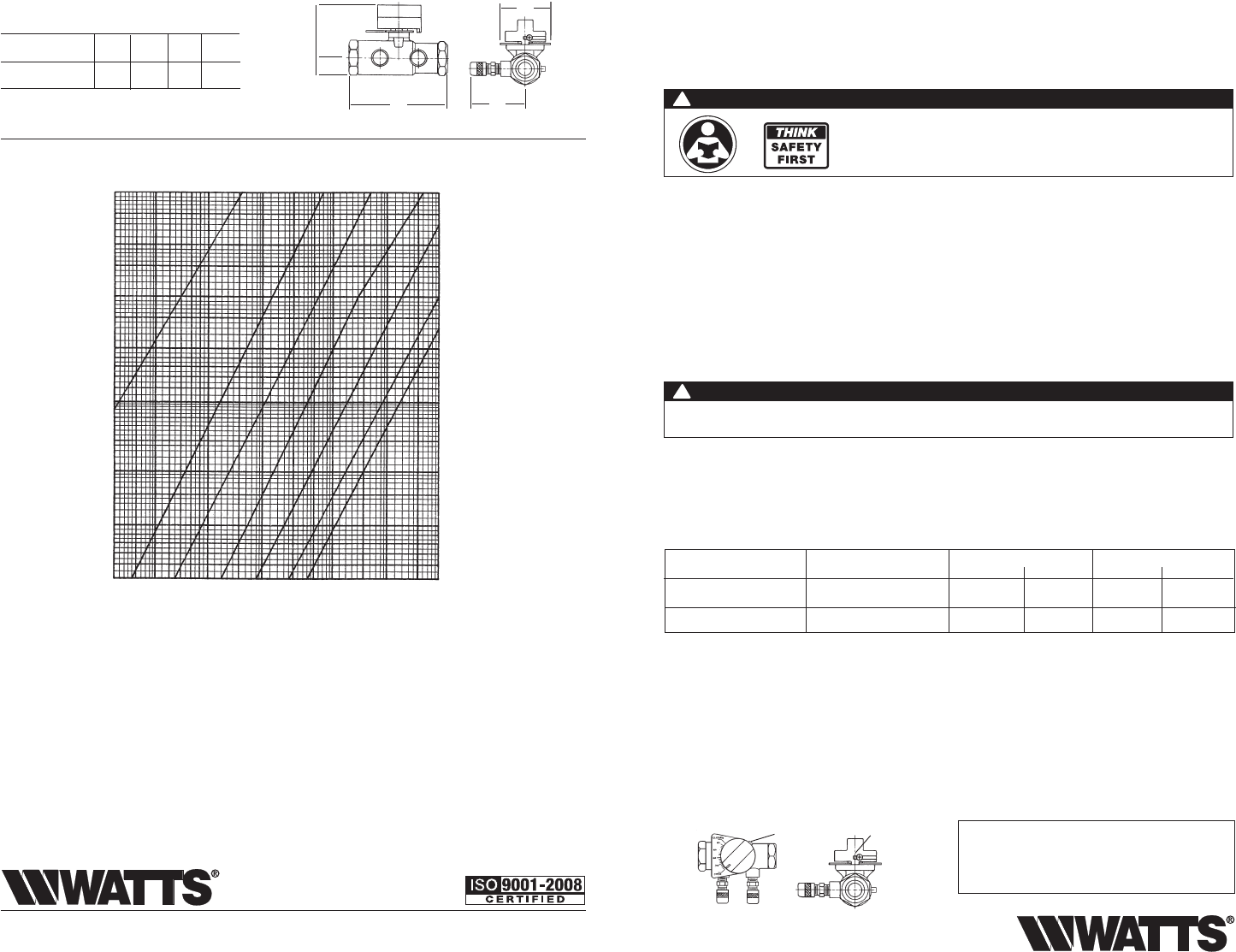
1" Flow Chart
Dial Setting
Pressure Differential
Pressure Differential
.3 .5 1.0 2.0 3.0 5.0 10.0 20.0 gpm
1.1 1.9 3.8 7.6 11.4 19 38 76 lpm
* To convert to kg/m
2
multiply feet of water by 304.8
*To convert to psi multiply feet of water by .4335
FLOW
70 60 50 40
30
20
0
Limited Warranty: Watts Regulator Co. (the “Company”) warrants each product to be free from defects in material and workmanship under normal usage for
a period of one year from the date of original shipment. In the event of such defects within the warranty period, the Company will, at its option, replace or
recondition the product without charge.
THE WARRANTY SET FORTH HEREIN IS GIVEN EXPRESSLY AND IS THE ONLY WARRANTY GIVEN BY THE COMPANY WITH RESPECT TO THE PRODUCT.
THE COMPANY MAKES NO OTHER WARRANTIES, EXPRESS OR IMPLIED. THE COMPANY HEREBY SPECIFICALLY DISCLAIMS ALL OTHER WARRANTIES,
EXPRESS OR IMPLIED, INCLUDING BUT NOT LIMITED TO THE IMPLIED WARRANTIES OF MERCHANTABILITY AND FITNESS FOR A PARTICULAR PURPOSE.
The remedy described in the first paragraph of this warranty shall constitute the sole and exclusive remedy for breach of warranty, and the Company shall
not be responsible for any incidental, special or consequential damages, including without limitation, lost profits or the cost of repairing or replacing other
property which is damaged if this product does not work properly, other costs resulting from labor charges, delays, vandalism, negligence, fouling caused by
foreign material, damage from adverse water conditions, chemical, or any other circumstances over which the Company has no control. This warranty shall
be invalidated by any abuse, misuse, misapplication, improper installation or improper maintenance or alteration of the product.
Some States do not allow limitations on how long an implied warranty lasts, and some States do not allow the exclusion or limitation of incidental or conse-
quential damages. Therefore the above limitations may not apply to you. This Limited Warranty gives you specific legal rights, and you may have other rights
that vary from State to State. You should consult applicable state laws to determine your rights. SO FAR AS IS CONSISTENT WITH APPLICABLE STATE
LAW, ANY IMPLIED WARRANTIES THAT MAY NOT BE DISCLAIMED, INCLUDING THE IMPLIED WARRANTIES OF MERCHANTABILITY AND FITNESS FOR A
PARTICULAR PURPOSE, ARE LIMITED IN DURATION TO ONE YEAR FROM THE DATE OF ORIGINAL SHIPMENT.
IS-CSM-61M1-S 1336 EDP# 1910821
USA: Tel. (978) 688-1811 • Fax: (978) 794-1848 • www.watts.com
Canada: (905) 332-4090 • Fax: (905) 332-7068 • www.wattsca
A Watts Water Technologies Company
WARNING: This product contains chemicals known
to the State of California to cause cancer and birth
defects or other reproductive harm.
For more information: www.watts.com/prop65
WARNING
!
Read this Manual BEFORE using this equipment.
Failure to read and follow all safety and use information can result in death,
serious personal injury, property damage, or damage to the equipment.
Keep this Manual for future reference.
Pressure - Temperature Limits
Maximum Pressure
Pattern Type of Solder Working Temp.
°F °C psi bar
200
250
93
121
125
300
8.6
20.7
95.5
(Tin-Antimony)
Solder-to-Solder
(Lead Free*)
Thread-to-Thread
© Watts, 2013
IS-CSM-61M1-S
WARNING
!
Use caution when soldering. Protect yourself and others. FUMES AND GASES can be hazardous to your health.
HEAT RAYS (INFRARED RADIATION) from flame or hot metal can injure eyes.
*The wetted surface of this product contacted by consum-
able water contains less than 0.25% of lead by weight.