
Specifications


X, P, and K 11644A 5-13
Performance Verification
System Operation Checks
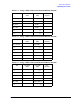
9. Record the maximum peak-to-peak value in the appropriate table on page 5-15.
10. Turn off the delta marker mode.
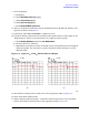
11. Repeat this procedure from step 6, and make an S
22
measurement on the standard
section. Record the measured value in the appropriate table on
page 5-15.
The S
11
and S
22
of a Thru Measurement
1. Verify that the calibration is still on.
2. Connect the standard section to ports 1 and 2 to form a thru connection.
3. To set the display:
a. Press [MEAS] and select Refl: FWD S11.
b. Press [SCALE REF] [10] [x1].
c. Select REFERENCE POSITION and press [10] [x1].
d. Select REFERENCE VALUE and press [0] [x1].
e. Press [MEAS] and select MEASURE RESTART.
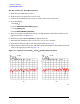
4. After one complete measurement sweep, the displayed trace should look similar to the
typical corrected trace shown in
Figure 5-4.
5. Determine the maximum value on the trace (you can use a marker).
6. Record the maximum value in the appropriate table on page 5-15.
7. Repeat this procedure from step 3, and make an S
22
measurement. Record the
measured value in the appropriate table on
page 5-15.
The S
21
and S
12
of a Thru Measurement
1. Verify that the calibration is still on.
2. Connect the standard section to ports 1 and 2 to form a thru connection.
3. To set the display:
a. Press [MEAS] and select Trans: FWD S
21
.
b. Press [SCALE] [.02] [x1].
c. Select REFERENCE POSITION [5] [x1].
d. Select [REFERENCE VALUE [±.2] [5] [x1].
e. Press [MEAS] and select MEASURE RESTART.
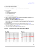
4. After one complete measurement sweep, the displayed trace should look similar to the
typical corrected trace shown in
Figure 5-5.
5. If necessary, select Press to Continue to update the trace.
6. Determine the greatest peak-to-peak deviation (this is any positive peak to any
adjacent negative peak). You can use the markers, as described in the first test, to
determine the peak-to-peak value.