
Specifications

RT9 Powershelf Rectifier Technologies
158-1806-01.doc
11 2-Mar-06
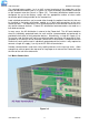
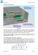
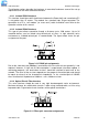
The switched battery cables (-ve in a –48V system) terminate on the copper bars of the
battery distribution module (item 2 in Figure 2.3), while the battery return cables terminate
on the common return bar (item 3 in Figure 2.3). The battery distribution module can be
configured for up to four battery strings with the appropriate number of return cable
termination points being available on the common bar.
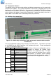
Load switched connections can be made either through the optional load circuits that can
be installed in the battery distribution module, or as bulk load connections to the main
rectifier busbars. The load return is then terminated either on the common return bar or on
the rectifier common busbars. External DC distribution feed connections are made as a
bulk load connection.
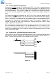
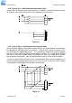
In many cases, the AC distribution is external to the Powershelf. The AC feed should be
wired as individually protected feeds for each rectifier (recommended and preferred) to
provide discrimination of fault protection devices. Alternatively, a single AC supply (1φ or
3φ) can be used, but there will not be any discrimination and if one unit generates a fault,
the power to all rectifiers will be removed. Where the AC distribution is integrated into the
Powershelf, each rectifier feed is individually protected and the installer is only required to
connect a single AC supply (1φ or 3φ) to the AC DIN rail terminations.
Remote communications and alarm relay cabling connects to the top rear cover. Allow
enough free cable to permit the top cover to hinge open or to remove the Powershelf from
the front of the rack for maintenance.
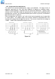
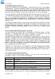
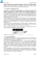
3.3 Mains Connections
Figure 3.4