
Specifications

RT9 Powershelf Rectifier Technologies
158-1806-01.doc
16 2-Mar-06
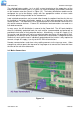
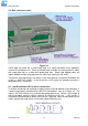
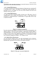
Figure 3.10
3.6 Battery connections
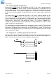
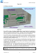
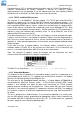
Figure 3.11
For –48VDC systems, the battery negative cables are terminated on the switched line
terminals of the battery distribution module (shown above), while the battery positive
cables are all tied to the common return bar. The cables can be either brought out through
the cut out adjacent to the return bar, or through the break-out slot in the top cover.
For +24VDC systems, the battery positive cables are terminated to the battery distribution
module, and the negative cables are tied to the common return bar. The internal wiring of
the +24VDC systems is different to that shown in the figure only in the swapping of the
polarity of the live and common DC lines.
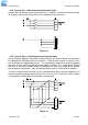
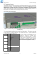
In standard Powershelf systems, not all of the 4 possible battery connection strings are
installed. The figure shows a battery distribution unit fitted with all the optional battery
strings possible. See BDM section below for details about adding extra battery strings or
load distribution lines to the BDM.
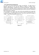
The M4 terminations at one end of the common return bar are available for connection of
the “central office earth” – the single point connection where the DC system is tied to the
building earthing system. This cable must be sized accordingly to carry the battery short
circuit current for the time required to clear the battery protection devices.
Note: Ensure the battery circuit breakers are open before connecting the batteries.
Connect the switched cable connections first, followed by the common return cable
connections.