
Specifications

RT9 Powershelf Rectifier Technologies
158-1806-01.doc
17 2-Mar-06
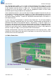
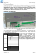
3.7 Temperature Sensors
The optional sensors for measuring ambient and battery temperature are the same device
(Part No. 804-1100-01). The system auto-detects if the sensor is plugged into one of the
positions (4) or (5) shown in Figure 2.4. If no sensor is installed, the MiniCSU-3 will show
“Not Available” in the menu items for the temperature measurements. Locate the ambient
sensor close to the intake air zone of the Powershelf. Locate the battery sensor on a
battery block in the middle shelf of the battery bank (likely hot zone).
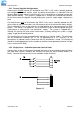
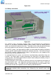
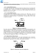
3.8 Auxiliary relay connections
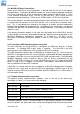
Figure 3.12 Alarm relay connections (right) and remote communications module
location (left)
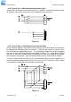
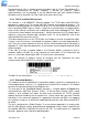
The user configurable auxiliary relays contacts are shown above. The contacts are rated
for 1A 250VAC or 1A 32VDC and have >1kV isolation to the coils. The pin configuration
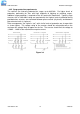
is: (Pin 1 at the right in Figure 3.12)
Relay # Pin # Pin function
1 N.O. (normally open)
2 N.C. (normally closed)
1
3 C (common)
4 N.O.
5 N.C.
2
6 C
7 N.O.
8 N.C.
3
9 C
10 N.O.
11 N.C.
4
12 C
13 N.O.
14 N.C.
5
15 C
The relays, being user configurable, can be
arranged to activate for multiple alarm
conditions or a single alarm only. The logic
can be inverted for individual relays so that
one becomes a controller failure indicator
(use the normally closed contact as this will
also indicate if the relay power has failed).