
Specifications

RT9 Powershelf Rectifier Technologies
158-1806-01.doc
18 2-Mar-06
3.9 MiniCSU-3 Power Connections
Power for the MiniCSU-3 and its peripherals is derived from the DC bus or the highest
charged battery. The Battery distribution module has reverse polarity protection circuit that
also serves to provide an “or-ing” of the highest supply voltage for the MiniCSU-3. There
is one common connection to the +VE bus (in the case of a –48V system) and one
connection each to the battery –VE bar on the LVDS and the –VE DC bus connection.
The system voltage is sensed and controlled solely on the connections to the DC bus (-VE
is sensed where it connects to the LVDS and the +VE is sensed on the common return
bar). This is considered close enough to the batteries to enable accurate temperature
compensated charging and long battery life. No additional user connections are required
to power the MiniCSU-3 or provide system voltage regulation, if the battery distribution
module is used.
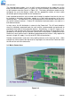
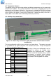
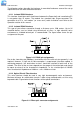
If the battery distribution module is not used, then the power for the MiniCSU-3 and the
system voltage sensing must be provided through the specially reserved connector on the
MiniCSU-3 backplane, indicated as connection (7) in Figure 2.4. DO NOT use this
connection if the battery distribution module is used, as it will cause a voltage sensing
conflict.
3.10 Front Panel USB Communications connection
The front USB port on the MiniCSU-3 is configured as USB-slave and has a B-type
connector. A standard USB A-to-B cable is required. The MiniCSU-3 can only
communicate via the USB port to a PC running the WinCSU-2 software.
The USB connection requires that a USB driver be installed on the PC. The first time the
MiniCSU-3 is plugged into the PC via the USB port, a Microsoft® Windows dialogue box
will appear asking the user to install the MiniCSU-3 USB Interface drivers. The Microsoft®
Windows operating system should be able to find the drivers automatically on the
WinCSU-2 CD-ROM, assuming it is in the CD-ROM drive of the PC. A copy of the USB
drivers is kept in the C:\Program Files\Rectifier Technologies Pacific\WinCSU-2\Driver
after installation of the WinCSU-2 software.
If WinCSU-2 is running when the unit is plugged in, a WinCSU-2 dialogue box will appear
asking the user if they wish to connect to the unit immediately. Otherwise the user will
need to select the MiniCSU-3 from the available MiniCSU USB devices in USB section in
the Connection Setup.
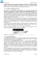
3.11 Remote Communication connection
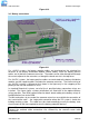
The optional remote communications modules, seen to the left of the alarm relay
connectors in Figure 3.12, can be one of the following:
P/N Description
152-1197-XX TCP/IP port
152-1209-XX WebCSU – TCP/IP, SNMP, Webpage, SNTP
152-1171-XX Opto-isolated RS-232
152-1172-XX Opto-isolated 4-wire RS-485
152-1173-XX Fibre Optic transceiver (RS-232 data protocol)
Embedded modems, either a standard modem or a point-to-point protocol (PPP) modem
can be installed in the spare holes with a similar mounting pattern to the alarm relay board.