
Specifications

RT9 Powershelf Rectifier Technologies
158-1806-01.doc
19 2-Mar-06
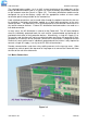
The following sections describe the interfaces in more detail and cover some of the set up
requirements for the more advanced interfaces.
3.11.1 Isolated RS232 Interface
This interface should be used if the distance between the Powershelf and a monitoring PC
is not greater than 15 meters. The module has standard 9-pin D-type connector. For
connection to a PC a “null modem” (or “cross-over”) cable should be used. Refer to the
Operation section of this manual.
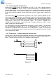
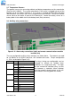
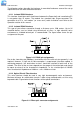
3.11.2 Isolated RS485 Interface
This type of port allows connection though a distance up to 1200 meters. Up to 32
standard devices can be linked using twisted pair of wires. In high electrical noise
environment a shielded twisted pair is recommended. The figure below shows the pin
assignment of the port.
Figure 3.13 RS485 pin assignments
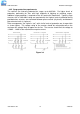
Due to the slow data rate (9600bps), termination of the line with resistors generally is not
required. However, if high rate of data corruption is experienced (slow data update in
monitoring program), line termination resistors should be installed at both ends of the
network. The value of the resistors depends on the gauge of the twisted pair and should
be equal (or closest) to line characteristic impedance. i.e. for a twisted pair of 24AWG
wires characteristic impedance of 100ohm – use a 100ohm resistor.
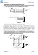
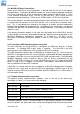
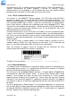
3.11.3 Optical Plastic Fibre Interface
This serial interface should be used in very high electromagnetic noise environment.
Maximum distance for reliable data transfer is 60m using standard cable, or 82m using
improved cable. Figure below shows functions of the optical terminations.
Figure 3.14 Fibre optic connector assignments