
Specifications

RT9 Powershelf Rectifier Technologies
158-1806-01.doc
21 2-Mar-06
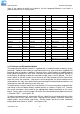
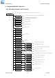
Note: If the country in which you intend to use the Integrated Modem is not listed, a
generic code ‘99’ or ‘FD’ can be tried.
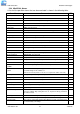
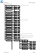
Country / Approval Code Country / Approval Code Country / Approval Code
Argentina Y 07 Iceland Y FD Philippines Y B5
Australia Y 09 India Y 99 (53) Poland Y FD (8A)
Austria Y FD (0A) Indonesia Y 99 Portugal Y FD (8B)
Belgium Y FD (0F) Ireland Y FD (57) Russia Y FD (B8)
Brazil Y 16 Israel Y B5 Singapore Y 9C
Canada Y B5 Italy Y FD (59) Slovakia Y FD
Chile Y 99 Japan Y 00 Slovenia Y FD
China Y B5 (26) Korea Y B5 (61) South Africa P 9F
Cyprus Y FD Latvia Y FD Spain Y FD (A0)
Czech Republic Y FD Lichtenstein Y FD Sweden Y FD (A5)
Denmark Y FD (31) Lithuania Y FD Switzerland Y FD (A6)
Estonia Y FD Luxembourg Y FD Taiwan Y FE
Finland Y FD (3C) Malaysia P 6C Thailand ….Y B5
France Y FD (3D) Malta Y FD Turkey Y FD
Germany Y FD (42) Mexico Y B5 (73) United Kingdom Y FD (B4)
Greece Y FD Netherlands Y FD (7B) United States Y B5
Hong Kong Y 99 (50) New Zealand Y 7E
Hungary Y FD Norway Y FD (82)
Approval: Y = yes ; P = in progress
Approval status in the table is indicated as declared by manufacturer on 15/12/2005.
3.12 Battery/Load Distribution Module
The battery/load distribution module is supplied with a standard number of battery strings
pre-wired. Optional extra battery or load connections may also have been supplied and
pre-wired from the factory as ordered. Servicing fuses, circuit breakers or adding optional
battery/load connection kits after initial installation and commissioning requires that the lid
of the battery distribution module be removed and top access can be gained. The lid is
held in place by two M3 screws at the front and will slide forward out of the Powershelf
once the screws are removed. If top access cannot be gained, the entire module can be
removed from the front after disconnecting and isolating the battery/load connections and
removing the single M5 mounting screw at the rear.
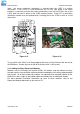
To add a battery string kit, mount the circuit breaker, DC current transducer, output busbar
and wiring in the next logical battery number position as shown in Figure 3.15. Connect
the current transducer signal cable to the appropriately labelled connector on the circuit
board. Finally, make sure the jumper link for the same numbered battery/load circuit alarm
is linked for “BAT”. (see Figure 3.16).
To add a load connection kit, connect the DC bus side of the circuit breaker directly to the
M6 stud on the DC bus side of the LVDS. Starting with the “Battery 4” position, mount the
output busbar, circuit breaker and wiring. Set the jumper link for the same numbered
battery/load circuit alarm to “LOAD”. (see Figure 3.16).