
Specifications
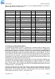

RT9 Powershelf Rectifier Technologies
158-1806-01.doc
22 2-Mar-06
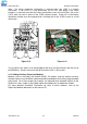
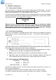
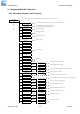
Note: the above connection information is relevant when the LVDS is a battery
disconnect. If the LVDS is a load disconnect, the DC bus side wiring of the circuit
breakers is reversed such that the battery connections come off the DC bus side of the
LVDS, while the load is taken off the LVDS common busbar. Diode V27 in the battery
distribution module must be replaced with a shorting link for the LVDS to work as a load
disconnect.
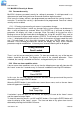
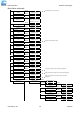
Figure 3.15 Figure 3.16
To re-install the lid, slide it in on the top edge of the base until the lid mates with the rear of
the BDM base. Secure the front of the lid to the base with 2 x M3 screws.
3.13 Adding Auxiliary Expansion Modules
Modules such as the battery cell monitor (BCM), AC monitor, and site monitor are daisy
chained from the unused ribbon cable connection provided on the Auxiliary programmable
relay board. All of these expansion modules are required to be mounted external to the
Powershelf, and a single 16-way ribbon cable connected to the available box-header.
For more detailed installation information for each of these modules, refer to the
Expansion Modules document on the manual CD.