
Specifications

RT9 Powershelf Rectifier Technologies
158-1806-01.doc
23 2-Mar-06
4. Commissioning
With all the batteries, load and AC cabling wired, and checked for correct polarity, the
system is commissioned by the following steps:
• Ensure no rectifiers are installed in the Powershelf and no load is applied.
• Close Battery breaker 1 and check (audible) that the LVDS closes.
• Plug in the MiniCSU-3 controller – it should power up off the battery. If not, it is
possible that the battery polarity is reversed.
• Set up the MiniCSU-3 menu items for:
o number of batteries and size (Ah),
o number of rectifiers,
o set the required float and equalize voltages,
o set LVDS option to Auto and set the LVDS Aux to “Normally Open”
o set the Battery Switch to “Normally Open”
o set the Cct Switch to “Normally Open”
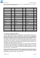
o set the Battery Transducer FS as: (24V systems)
Powershelf Transducer FS
PSLF-1100,-1110,(-1102) 50A
PSLF-1115,-1120,-1125,-1130,(-1112) 100A
(PSLF-1117,-1122,-1127) 200A
o set the amount of battery temperature compensation voltage adjustment if
used and after confirming that the battery temperature is being measured
o set the battery charging current limit to 10% of the Ah rating (ie if 150Ah
battery is used, set the limit to 15A) – this value can be adjusted later to meet
your specific charging requirements.
In many cases, these values are set up in the factory and will only require
modification if the particular battery being used requires a different set up.
• Close the remaining battery circuit breakers if more than one string is used.
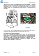
• Insert a switch-mode rectifier (SMR) in position 1 and apply the AC power. The
rectifier unit should power up and begin charging the battery bank/s.
• Insert all the remaining rectifiers (SMRs) and apply AC power to them.
• Check that the bus voltage is increasing toward the float voltage.
• Close the load circuit breakers and check that the loads power up.
• Wait for 1 minute and check that the rectifiers are all sharing the load current to
within +/-2A of the average rectifier current.
• The system is up and operational. Adjust any operational monitoring or setup
details as required (see the next section on Operation or refer to the MiniCSU-3
Operation Manual on the CD for a detailed explanation of the functions).