
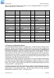
Specifications

RT9 Powershelf Rectifier Technologies
158-1806-01.doc
25 2-Mar-06
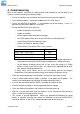
5.1 MiniCSU-3 Components
5.1.1 Alpha-numeric Display
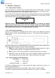
The user interface is a two-line by 16 character alphanumeric OLED display. The 5mm
high characters normally display output voltage and current as well as the system status -
Float (FL) or Equalise (EQ). This is the default or “home” screen.
If an activity such as battery discharge testing is being performed, the current and voltage
are always displayed, while the second line alternates between the system status (FL/EQ)
and the activity status, for example “BDT in progress”.
104A 54.5V
FL
Whenever there is no push-button activity for more than one minute, the display
always reverts to this home screen. Note: the examples shown are for 48V systems.
After a further 5 minutes the screen goes into a screen saver mode that is disabled
when either an alarm occurs or a front panel button is pushed.
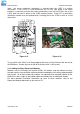
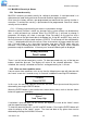
5.1.2 Front Panel Pushbuttons
There are six pushbuttons associated with the OLED screen for the purpose of entering
different Menus and for scrolling through the menus. The layout of the pushbuttons is
shown below:
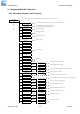
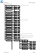
Apart from the base menu (system parameters), there are three other menus which can be
accessed by momentarily pressing the relevant pushbuttons:
a) SMR menu, which includes the rectifier related programmed parameters as well as
the output current and heat-sink temperature for each rectifier;
b) Battery menu in which all the parameters relating to the batteries are found;
c) Log which stores the individual alarm event information together with date and
time starting with the most recent alarm. A total of 100 alarms are stored.
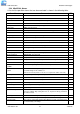
5.1.3 Status Indicating LEDs (MiniCSU-3)
SYSTEM OK
Green LED
ALARM
!
Amber LED
SMR SHUTDOWN
Red LED
All LEDs off, indicates the unit is off due to either DC power not present, or there is an
internal failure of MiniCSU-3
The amber LED indicates any alarm condition, either system or rectifier related.
The red LED indicates that one or more of the rectifiers in the system is shut down.