
Specifications

RT9 Powershelf Rectifier Technologies
158-1806-01.doc
9 2-Mar-06
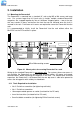
3.1.2 Gaining Access to Rear Wiring
NOTE: Access to the rear wiring should be limited to qualified service personnel. It is
recommended to remove the AC power before gaining access to the rear wiring due to the
safety hazard present inside the electrical enclosure. Similarly, the energy hazard
associated with the batteries connected to the DC bus must be addressed through the use
of appropriately insulated tools and other measures to prevent accidental short circuits to
the DC bus.
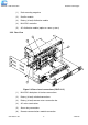
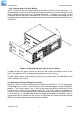
Figure 3.2 Opening top rear cover to access wiring
To open the top rear cover, remove the two rear M3 screws securing the cover to the
back. The top cover will then hinge up to provide access to the wiring.
To gain further access to the wiring, remove the rear cover grills by removing the two
screws holding each 1U grill.
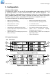
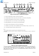
3.2 Overview of External Wiring Connections
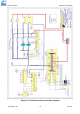
Figure 3.3 shows the internal and interface schematic for the PSLF-1115. For the purpose
of indicating how a system is connected, the same schematic applies to other Powershelf
products. The system shown is for a –48V system where the positive side of the DC bus
is tied to earth, usually on the common return bar. For +24V systems, the opposite is
usually the case with the negative DC bus being connected to the common return bar that
is in turn earthed. It is also possible to float the output, but under these conditions, there is
no guarantee that all voltages on the DC bus will stay below the Safety Extra-Low Voltage
(SELV) limits with respect to earth during fault conditions.