
Operating instructions


4
11
1
VAC
6
mA
10A
A
4
5
3
2
10A
μ
Hz
%
MAX
MIN
8
7
10
9
VDC
TEMP
Ω
CAP
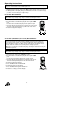
Controls and Jacks
1. 6,000 count LCD display
2. RANGE button
3. Hz and % button
4. Mode button
5. Function switch
6. mA, µA and 10A input jacks
7. COM input jack
8. Positive input jack
9. HOLD and Backlight button
10. RELATIVE button
11. MAX/MIN button
Note: Tilt stand and battery compartment are on rear of unit.
Note: Input Jacks for test probes are a firm fit to prevent dislocation. Take care to fully
insert banana plug into jack.
Symbols and Annunciators
Auto power off
•))) Continuity
Diode test
Battery status
n nano (10
-9
) (capacitance)
µ micro (10
-6
) (amps, cap)
m milli (10
-3
) (volts, amps)
A Amps
k kilo (10
3
) (ohms)
F Farads (capacitance)
M mega (10
6
) (ohms)
Ohms
Hz Hertz (frequency) V Volts
% Percent (duty ratio) REL Relative
AC Alternating current AUTO Autoranging
DC Direct current HOLD Display hold
ºF Degrees Fahrenheit ºC Degrees Centigrade
MAX Maximum MIN Minimum