USER GUIDE CM52 Integrators’ Manual Reference: WI_DEV_CM52_UGD_001 Version: 001 Date: June 20, 2007
CM52 Integrators’ Manual Trademarks ®, WAVECOM®, WISMO®, Open AT®, Wireless CPU®, Wireless Microprocessor® and certain other trademarks and logos appearing on this document, are filed or registered trademarks of Wavecom S.A. in France or in other countries. All other company and/or product names mentioned may be filed or registered trademarks of their respective owners. Copyright This manual is copyrighted by WAVECOM with all rights reserved.
CM52 Integrators’ Manual Table of Contents 1 Introduction to the Integrator’s Manual ............................................................ 9 1.1 OVERVIEW ............................................................................................................................... 9 1.2 HOW TO READ THE MANUAL ................................................................................................... 9 1.3 SERVICE AND SUPPORT..................................................................
CM52 Integrators’ Manual 2.4.3 2.4.3.1 2.4.3.2 2.4.3.3 2.4.4 POWER CONSUMPTION ................................................................................................ 23 VCC_MAIN SUPPLY POWER CONSUMPTION................................................................... 24 VCC_AUX SUPPLY POWER CONSUMPTION..................................................................... 24 POWER DOWN MODE (MINIMUM DC POWER CONSUMPTION) ........................................ 25 VREF SIGNAL DETAILS .........
CM52 Integrators’ Manual 3.4.4 LOUDSPEAKER PATH ................................................................................................... 46 3.5 SYSTEM CONNECTOR IO FUNCTIONALITY .............................................................................. 47 4 Functional Description ................................................................................... 49 5 Hints for Integrating the Wireless CPU® .......................................................... 50 5.1 PRECAUTIONS .
CM52 Integrators’ Manual List of Tables TABLE 1: ABBREVIATION DEFINITIONS ................................................................................................ TABLE 2: SYSTEM CONNECTOR AND MATING PART NUMBERS ..................................................................... TABLE 3: PIN-OUT OF THE SYSTEM CONNECTOR HEADER........................................................................... TABLE 4: CMOS OUTPUT / INPUT ELECTRICAL CHARACTERISTICS .........................................
CM52 Integrators’ Manual List of Figures FIGURE 1: CM52 PRIMARY SIDE ........................................................................................................ FIGURE 2: CM52 SECONDARY SIDE ..................................................................................................... FIGURE 3: MECHANICAL DIMENSIONS DRAWING (CM52003 VARIANT) ...................................................... FIGURE 4: MECHANICAL DIMENSIONS DRAWING (CM52001 AND CM52004 VARIANTS)......................
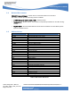
CM52 Integrators’ Manual Revision History Release Date Summary of Changes PA1 PA2 PA3 PA4 PA5 PA6 05/07/2004 09/01/2004 11/17/2004 11/29/2004 12/01/2004 06/16/2005 A PB1 09/15/2005 11/30/2005 PB2 PB3 02/16/2006 03/08/2006 PB4 03/16/2006 PB5 03/22/2006 B PC1 PC2 03/24/2006 06/02/2006 06/13/2006 001 06/20/2007 Initial Draft Formatting Updated Chapters 1 & 2 Updated with review feedback Updated the List of Tables and Figures Current Consumption Table, RTC Block Diagram, Mechanical Drawing Rel
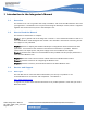
CM52 Integrators’ Manual 1 Introduction to the Integrator’s Manual 1.1 Overview This manual is for use as a guide to the setup, installation, and use of the CM52 Wireless CPU® into your application. The Wireless CPU® may be tested using the developer’s board, which is supplied together with all the necessary tools in the Developer’s Kit. 1.2 How to Read the Manual This manual is divided into six chapters: Chapter 1 gives a general view of the integrator’s manual.
CM52 Integrators’ Manual 1.4 Related Documents CM52 AT Command Manual – Details the AT command interface for the CM52 The CM52 is based upon the following mobile standards: IS-2000 Release 0 (1XRTT), MOB_P_REV – CDMA protocol TIA/EIA/IS-91 – Mobile Station – Base Station Compatibility Standard for 800 MHz Analog Cellular TIA/EIA-98-D – Recommended Minimum Performance Standards for Dual-Mode Spread Spectrum Mobile Stations 1.
CM52 Integrators’ Manual 2 Integrating the CM52 Wireless CPU® 2.1 Overview The CM52 is a dual band, dual mode CDMA transceiver Wireless CPU®. It operates in the 800 MHz band for CDMA and AMPS and in the 1900 MHz band for CDMA. It is designed for consumer and OEM industrial voice and data applications. The CM52 Wireless CPU® is intended for mounting into an application developer’s chassis to provide wireless communication capability for the product.
CM52 Integrators’ Manual Note! All the measurements are in millimeters. Figure 3: Mechanical Dimensions Drawing (CM52003 variant) CM52 Integrators’ Manual WI_DEV_CM52_UGD_001-001 Page 12 of 53 This document is the sole and exclusive property of WAVECOM. Not to be distributed or divulged without prior written agreement. Ce document est la propriété exclusive de WAVECOM.
CM52 Integrators’ Manual Note! All the measurements are in millimeters. Figure 4: Mechanical Dimensions Drawing (CM52001 and CM52004 variants) CM52 Integrators’ Manual WI_DEV_CM52_UGD_001-001 Page 13 of 53 This document is the sole and exclusive property of WAVECOM. Not to be distributed or divulged without prior written agreement. Ce document est la propriété exclusive de WAVECOM.
CM52 Integrators’ Manual Note! All the measurements are in millimeters. Figure 5: Mechanical Dimensions Drawing (CM52002 variant) CM52 Integrators’ Manual WI_DEV_CM52_UGD_001-001 Page 14 of 53 This document is the sole and exclusive property of WAVECOM. Not to be distributed or divulged without prior written agreement. Ce document est la propriété exclusive de WAVECOM.
CM52 Integrators’ Manual Note! All the measurements are in millimeters. Figure 6: Keep-out drawing of CM52 CM52 Integrators’ Manual WI_DEV_CM52_UGD_001-001 Page 15 of 53 This document is the sole and exclusive property of WAVECOM. Not to be distributed or divulged without prior written agreement. Ce document est la propriété exclusive de WAVECOM.
CM52 Integrators’ Manual 2.2.2 Heat-Sink Requirements The application is required to provide a heat-sink for the 3W AMPS capabilities of the CM52. The application should be designed to provide a heat sink with a thermal resistance of 4.0 °C/W. For applications that disable the 3W mode (Class I) and only operate in 0.6W mode (Class III) a heat-sink is not required. 2.2.
CM52 Integrators’ Manual 2.2.3.2 Mounting Configuration B Mounting configuration “B” uses four 3/4 mounting holes that support #6 size screws. Figure 8: Mounting Configuration B Note: This is the recommend mounting configuration due to the higher mechanical vibration specification supported. 2.2.4 RF Connector Mounting Considerations When designing the application the designer should ensure that the housing does not degrade the RF performance of the CM52.
CM52 Integrators’ Manual 2.3 System Connector Interface 2.3.1 Mechanical Overview External interfaces to the Wireless CPU® are made primarily through a 40 pin, standard 0.050-inch pitch, ODU header show below. Figure 10: 40-Pin System Connector Figure 11: 40-Pin System Connector Pin Numbering Description ODU Part Number Dimension A Dimension B System Connector Mating Ribbon Connector SMT Mating Header Ribbon cable, AWG 30 515.569.035.140.xxx 525.060.035.040.xxx 24.13 mm 22.86 mm 525.041.035.
CM52 Integrators’ Manual 2.3.
CM52 Integrators’ Manual Pin Signal Description Dir Pin Type 25 26 27 28 29 30 31 32 33 34 35 36 37 38 39 40 CTS DTR TD RTS VCC_AUX RD VCC_AUX VCC_AUX VCC_MAIN VCC_MAIN SDA_SPI_IN SCL_SPI_CLK SYS_DTM_2 SPI_OUT SYS_DFM_2 RI Clear to send Data Terminal Ready Transmit data, also known as DTMS Request to Send 13.8 VDC supply input Receive data, also known as DFMS 13.8 VDC supply input 13.
CM52 Integrators’ Manual 2.3.3 Logic Levels Many of the signals present in the interface are CMOS signals where the following levels apply. The nominal voltage level for the CMOS signals is 2.9 V. Drive capability of the outputs is also indicated. Parameter Test Conditions High level output voltage (IOH = 800 µA) Low level output voltage (IOL = 800 µA) High level input voltage Low level input voltage VOH VOL VIH VIL Limits Min 2.45 0 1.9 0 Units Max 3.1 0.45 3.1 0.
CM52 Integrators’ Manual The following table summarizes the power supply requirements from the application. Input Supply VCC_MAIN VCC_AUX VRTC(no GPS) VRTC(with GPS) Voltage (Volts DC) 5.00 ± 10% 13.8 ± 20% 1.8 to 3.9 3.4 to 3.9 Max. Current (Amps) Max. Ripple (mVpp) Operation 0- 4KHz 1.4 1.3 1.2 uA 500 uA 100mVpp 600mVpp 4 KHz10MHz 50mVpp 240mVpp Table 6: CM52 Power Supply Requirements 2.4.
CM52 Integrators’ Manual 2.4.2 Power Supply and Ground Signals 2.4.2.1 Power Supply Signal Pins Following is a list of the power supply pins: Pin Signal Description 4 4 VRTC 1.8 V to 3.9V ( 3.4V to 3.9V if GPS mounted) 29 VCC_AUX 13.8 volt ± 20% 31 32 33 34 VCC_AUX VCC_AUX VCC_MAIN VCC_MAIN 13.8 volt ± 20% 13.
CM52 Integrators’ Manual 2.4.3.1 VCC_MAIN Supply Power Consumption Parameter Min Typical Max Units Input Voltage 4.5 5 5.5 V In AMPS Call on Power Level 0 (Power Class I) In AMPS Call on Power Level 2 0.62 0.82 A 0.94 1.4 A In CDMA call-Cellular Mode 0.77 1.2 A In CDMA call-PCS Mode 0.84 1.3 A CDMA burst duration for Network update 1.2 s Standby/Idle Current Draw in Slotted Mode (CDMA) 1.28 sec slot 9.6 mA 2.56 sec slot 7.2 mA 5.12 sec slot 4.
CM52 Integrators’ Manual Parameter Min Typical Max Units Input Voltage 11 13.8 16.6 V In a Call on Power Level 0 (Power Class I) 0.88 1.3 A In a Call on Power Level 2 3.5 4.5 mA AMPS Burst Duration for network update 0.16 Stand-by/Idle mode (Rx ON) 0.5 Powered Down Current Draw 1 S 1 uA uA Table 12: VCC_AUX Supply Power Consumption Note: The typical values observed are made in AMPS call with voice channel set to 358. 2.4.3.
CM52 Integrators’ Manual Parameter Minimum Typical Maximum Units Supply Voltage Reference 2.45 2.9 3.1 V 1000 uA Output Current Application Load 10 100 KΩ Rise Time 3300 us Fall Time 0.8 ms Table 14: VREF Supply Details 2.5 Real Time Clock (RTC) Circuit The real time clock is a feature provided by the CM52 that allows the Wireless CPU® to sleep and wakeup for a definable number of cycles, as configured by the host application. This feature is an optional hardware feature.
CM52 Integrators’ Manual Figure 12: RTC Functional Block Diagram 2.6 Audio Interface The audio-related signals are: the analog audio signals ATMS (Audio to Mobile Station), AFMS (Audio from Mobile Station), PCM (Pulse Code Modulation) signals (PCMULD, PCMDLD, PCMCLK, and PCMSYNC). Pin Signal Description 7 AFMS Audio Output From Wireless CPU®. 10 ATMS Audio Input to Wireless CPU®. 9 AGND Analog Reference 17 PCMCLK PCM Clock Output from Wireless CPU®.
CM52 Integrators’ Manual 2.6.1 Digital Audio The CM52 provides digital audio capability over the system connector. The digital audio signals enable the connection of a digital audio source. The receiver is bypassing the analog audio processing functions performed within the Wireless CPU®. The digital audio interface includes the following PCM signals: Pin Signal Description 17 PCMCLK PCM Clock Output from Wireless CPU®.
CM52 Integrators’ Manual 2.6.1.2 Timing Timing shall be according to the following diagram (see Figure 13: PCM Timing Diagram). The signals in the diagram shall be interpreted according to the following relation. Figure 13: PCM Timing Diagram The meaning and value of the timing parameters are described in Table 18. Name Description tSYNC PCM_SYNC cycle time. tSYNCA tSYNCD tSU(SYNC) tH(SYNC) tCLK tCLKH tCLKL tPDLD TSU(ULD) TH(ULD) Min PCM_SYNC frequency PCM_SYNC asserted time.
CM52 Integrators’ Manual 2.6.2 Analog Audio ATMS is the analog audio input to the Wireless CPU®. When it is active, it is connected to the radio via the audio processing stages in the Wireless CPU®. The AFMS is the analog audio output from the Wireless CPU®. When it is active it is connected to the radio via the audio processing stages in the Wireless CPU®. The AGND is the analog reference signal.
CM52 Integrators’ Manual Analog Reference (AGND) The AGND lead is the analog audio reference ground. It is the return signal for Audio To Mobile Station (ATMS), Audio From Mobile Station (AFMS). Electrical characteristics: Imax < 40 mA (peak) The AGND is connected to the chassis Ground (GND) in the CM52 Wireless CPU®, and only there. The application should be connected to GND and only use AGND as reference for the audio lines ATMS and AFMS.
CM52 Integrators’ Manual Figure 15: Microphone Implementation Example The microphone should preferably be connected to its pre-amplifier differentially which will minimize noise pickup from possible ground current. AFMS: An application using the analog audio interface must re-reference the AFMS-signal from AGND to its own internal BIAS. The figure shows a differential implementation. C1 is chosen to create the correct HP frequency response.
CM52 Integrators’ Manual 2.7 Serial Data Interface The serial channels are used as asynchronous communication links between the application system and the Wireless CPU®. The following table shows the serial data channels related signals: Pin Signal Description Dir 23 DCD O 25 CTS 26 DTR 27 TD 28 RTS 30 RD Data Carrier Detect This signal is set default high. It goes low indicating that a data call is established (CONNECT received from the remote modem).
CM52 Integrators’ Manual 2.8.1 Antenna Connector A variety of antenna connectors are available for the CM52 Wireless CPU® including SMA, SMB, and MCX. A standard 5-pin, thru-hole pattern has been selected because of the wide variety of compatible connectors available and also for the maximum mechanical strength.
CM52 Integrators’ Manual Figure 18: Sample SMA Connector and Mounting Hole Electrical performance parameters are valid only when the terminating impedance at the output of the antenna connector exhibits a VSWR of less than 2:1 for all phase angles in the frequency band of operation.
CM52 Integrators’ Manual Mobile Station Power Level (dBm) 0 1 2 3 4 5 6 7 Class I, AMPS 34.8 31 26.3 24 20 16 12 8 Class III, AMPS 26.3 26.3 26.3 24 20 16 12 8 Table 23: Mobile Station Nominal Analog Power Levels Note: These numbers represent the Nominal Output Power 5 in AMPS mode and are referenced to the antenna connector. Analog output power levels are as defined for a Power Class I device in Industry Specification EIA/TIA IS-91.
CM52 Integrators’ Manual Figure 19: Antenna Diagnostic Circuit The current antenna status is based on a comparison between the voltage measured at the antenna connector and the limits set by the application for OPEN and SHORT. Because of the tolerances associated with Wireless CPU® power supply, ADC power supply and the ADC itself, there will be a correction factor in the ADC reading as listed below in Table 25.
CM52 Integrators’ Manual 3 Recommended Interface Circuitry Abbreviations: VCC - Represents the logic supply voltage used by the application. VREF_CA- Current amplified reference voltage used for all logic interface circuitry to the CM52. Component proposals: Transistors not showing a base resistor should be interpreted as a BRT (Built in Resistor Transistor) i.e. Toshiba RN1308. 3.1 The inverting buffers should preferably be Schmitt-Triggered, i.e. Toshiba TC7S14 or similar.
CM52 Integrators’ Manual Application Phone Module 12, MODULE_PWR_EN_B 0 = Phone Module Power OFF 1 = Phone Module Power ON 5V 5V 0 -10 ohm 0 - 1k 0 2, VREF + 1M VREF_CA 10uF 100 Shutdown Indicate 15, HW_SD Shutdown Request VCC 1 - 100k Ring Indicator VREF_CA 40, RI Figure 20: Status Group Diagram 3.1.1 MODULE_PWR_EN_B This signal, located on pin 12 in the system connector, enables the main 5V supply in the phone Wireless CPU® so that it powers on.
CM52 Integrators’ Manual 3.1.3 RI This signal, located on pin 40 in the system connector, provides the application with notification of an incoming call or SMS. Please refer to the CM52 Software User’s Guide and AT Command Manual for more details about what events can toggle this signal. It takes approximately three seconds for the Wireless CPU® to be ready to receive data after it is powered ON by pulling the MODULE_PWR_EN_B signal low.
CM52 Integrators’ Manual Shut down sequence 1. To request a shutdown of the phone module, the application should provide an active low pulse of 100 ± 25 ms on the HW_SD pin through an open collector output. 2. This pulse is detected by the Wireless CPU®, which confirms the request by enabling its HW_SD output, setting it active low. 3. The application waits for the HW_SD pin to become inactive high. 4.
CM52 Integrators’ Manual 3.2 Data Group Recommended Circuitry The data group contains six signals: three output signals from application, two input signals to application, and one I/O signal. Phone Module Application VCC 1 - 100k VREF_CA RxD CTS 30, RD (DFMS) 25, CTS VREF_CA VREF_CA 27, TD (DTMS) 28, RTS 26, DTR 1 - 100k TxD RTS DTR VREF_CA VREF_CA 1 - 100k VPPFLASH_EN VCC 1 - 100k DCD VREF_CA 23, VPPFLASH/DCD 100k Figure 23: Data Group Diagram 3.2.
CM52 Integrators’ Manual 3.3 PCM Group Recommended Circuitry The PCM group contains four signals, three input signals to the application, and one output signal from the application. Figure 24: PCM Group Diagram CM52 Integrators’ Manual WI_DEV_CM52_UGD_001-001 Page 43 of 53 This document is the sole and exclusive property of WAVECOM. Not to be distributed or divulged without prior written agreement. Ce document est la propriété exclusive de WAVECOM.
CM52 Integrators’ Manual 3.4 Analog Audio Group Recommended Circuitry 3.4.1 Creating an analog ground An analog ground plane should be generated which connects to GND in one point so that high frequency digital current is not floating through the analog ground. Connecting the analog ground in only one point avoids ground currents from power supplies and other high current circuitry from creating noise in the analog circuitry.
CM52 Integrators’ Manual 3.4.2 Analog ground vs. AGND The AGND signal output from the Wireless CPU® is not a ground. It is an analog reference, connected to the main ground and used by the Wireless CPU® in one place inside the Wireless CPU®. Under any circumstances it should not be used as a ground or connected to application’s ground. AGND must be treated as a signal. Together with ATMS and AFMS it creates a semi differential interface.
CM52 Integrators’ Manual 3.4.4 Loudspeaker path An application using the analog audio interface must re-reference the AFMS-signal from AGND to its own internal BIAS. The figure shows a differential implementation. C1 is chosen to create the correct HP frequency response. R1 and R2 determine the gain, and C2 and R2 determine the LP frequency response.
CM52 Integrators’ Manual 3.5 System connector IO functionality Note 1: The application IO can be one of the following listed types: I Logic input (no pull up or pull down resistors required). IOC Logic open-collector input. O Logic output (no pull up or pull down resistors required). OOC Logic open-collector output. I/O Logic I/O. The pin direction in this table is referenced from the application’s point of view.
CM52 Integrators’ Manual Group Pin No Name Application Requirements App I/O 17 9 PCMCLK AGND I I 10 7 12 AUX1(ATMS) AUX0(AFMS) MODULE_PWR _EN_B 2 VREF 40 RI 24 RINGER 6 15 HW_SD Unused 39 37 36 35 38 4 3 1 OOC I I O IOC IOC O I/O I/O I/O Reserved 13 CFMS CTMS Reserved Reserved Reserved IO_4_VRTC IO_3_GPS_FIX IO_1_TIMEMAR K OUTPUT1 Logic input from phone module. Analog reference. This signal is an analog reference output by the phone module.
CM52 Integrators’ Manual 4 Functional Description The CM52 Wireless CPU® performs a set of telecom services according to TIA/EIA-IS-2000. The functions of the display and keypad, usually used to make calls, are implemented by issuing AT Commands over the serial interface. See the CM52 Software User's Guide and AT Command Manual for a complete functional description and user scenarios for the CM52.
CM52 Integrators’ Manual 5 Hints for Integrating the Wireless CPU® This section, which gives you advice and helpful hints on how to integrate the CM52 with the application, should be taken as a guide. Note! The circuits on the test board are not shielded. Therefore take proper precautions for avoiding ESD and EMI. 5.1 Precautions Following is a list of preparations that you should make before beginning the integration work that is described in this section. 5.
CM52 Integrators’ Manual 5.4 Antenna 5.4.1 Antenna Type When choosing an antenna for your application you must consider the following requirements: The antenna must be designed for the AMPS/CDMA 800 and CDMA 1900 MHz frequency band (dual band) for the CM52. 5.4.2 The impedance of the antenna and antenna cable must be 50 Ω. The VSWR value should be less than 2:1. Antenna Placement Always follow the instructions supplied by the antenna manufacturer.
CM52 Integrators’ Manual 6 Technical Data Mechanical specifications Maximum length: 114 mm Maximum width: 49.50 mm Maximum thickness: 18.97 mm Weight: 68.2 g Power supply voltage, normal operation VCC_MAIN VCC_AUX Nominal Voltage: 5.00 Volts 13.8 Volts Voltage range: 4.50 – 5.50 Volts 11.0 – 16.
CM52 Integrators’ Manual Non-stationary vibration, including shock Bump: Shock response spectrum I, peak acceleration: - 4 shocks in each axis and direction: 300 m/s2, 11 ms Acceleration 250 m/s2 Free fall transportation: 1.
APPLICATION NOTE GR/GS64 Charging Interface Page: 1/1 WAVECOM S.A. - 3 esplanade du Foncet - 92442 Issy-les-Moulineaux Cedex - France - Tel: +33(0)1 46 29 08 00 - Fax: +33(0)1 46 29 08 08 This document is the and exclusive of WAVECOM. to be distributed or divulged prior agreement. Wavecom, Inc. sole - 430 Davis Drive property - Suite 300 - ResearchNot Triangle Park, NC 27709 - USAwithout - Tel: +1 919written 237 4000 - Fax: +1 919 237 4140 nd Bio-Informatics Centreou - No.