
User guide

CM52 Integrators’ Manual
CM52 Integrators’ Manual
WI_DEV_CM52_UGD_001-001
Page 33 of 53
This document is the sole and exclusive property of WAVECOM. Not to be distributed or divulged without prior written agreement.
Ce document est la propriété exclusive de WAVECOM. Il ne peut être communiqué ou divulgué à des tiers sans son autorisation préalable
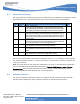
2.7 Serial Data Interface
The serial channels are used as asynchronous communication links between the application system
and the Wireless CPU
®
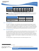
. The following table shows the serial data channels related signals:
Pin Signal Description Dir
23 DCD Data Carrier Detect
This signal is set default high. It goes low indicating that a data
call is established (CONNECT received from the remote modem).
The signal goes high when the data connection is disconnected.
O
25 CTS Clear To Send
This signal is initially set high indicating that the Wireless CPU
®
is
not ready to receive data. It is set low after the Wireless CPU
®
is
done performing its startup procedure indicating that it is ready to
receive data.
O
26 DTR Data Terminal Ready
This signal should be set low by the application during a data call.
A low to high transition will terminate the data call.
I
27 TD Transmit Serial Data To Wireless CPU
®
(DTMS)
The application shall set this signal high at startup.
I
28 RTS Request To Send
The application shall set this pin low when it is ready to receive
data.
I
30 RD Receive Serial Data From Wireless CPU
®
(DFMS)
The Wireless CPU
®
will set this signal high at startup.
O
Table 21: Serial Data Channels
The common CMOS electrical specifications defined in Section
1.1.1 are valid for all these signals.
The standard character format is 1 start bit, 8 data bits, non-parity and 1 stop bit. In all there are
10 bits per character.
Note! The signal levels do not match the standard RS-232 (V.28). If the application signal levels
are not compatible with the CMOS levels described in
Table 4: CMOS Output / Input Electrical
Characteristics
, then electrical protection level limiters or level conversion hardware will be
necessary between the CM52 Wireless CPU
®
and the application.
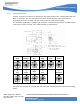
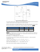
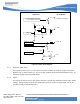
2.8 Antenna Interface
The antenna interface of the CM52 consists of a single or dual RF connector for the radio with
optional antenna diagnostics and a single RF connector for the optional GPS function.