GTR64 http://www.matrix.es/GTR64 GTR-64 TERMINAL Integrators Manual Intelligent, powerful, flexible and simple GSM Terminal in a box Powered by WAVECOM GR64 wireless CPU (legacy SonyEricsson M2M) GTR64 Integrators Manual V.1.2 Pag. 1 Preliminary.
GTR64 http://www.matrix.es/GTR64 Important information This technical description contains important information for start up and use of the GTR64 Terminal. Read it carefully before you start working with the GTR64 Terminal. The warranty will be void should damage occur due to non-compliance with these instructions for use. We cannot accept any responsibility for consequential loss. SECOND EDITION.
GTR64 http://www.matrix.es/GTR64 1. INTRODUCTION ................................................................................................................................................. 5 1.1 Description............................................................................................................................ 5 1.2 Highlights.............................................................................................................................. 6 1.
GTR64 6.3. 6.4. 6.5. 6.6. http://www.matrix.es/GTR64 SIM card precautions .......................................................................................................... 26 Antenna precautions ........................................................................................................... 26 Radio Frequency (RF) exposure and SAR .............................................................................. 26 Personal Medical Devices..................................................
GTR64 http://www.matrix.es/GTR64 1. INTRODUCTION 1.1 Description The GTR64 is an intelligent GSM/GPRS control terminal that encapsulates everything you need for wireless M2M capability in one compact unit. In conjunction with M2mpower package the GTR64 can host and control your wireless application, minimising the need for extra components. Alternatively, it can be used as a powerful standalone GPRS modem with its intrinsic TCP/IP stack.
GTR64 http://www.matrix.es/GTR64 1.2 Highlights Radio Features Quad Band GSM/GPRS GSM 850/900 Power class 4 (33dBm) GSM 1800/1900 Power class 1 (30dBm) Mobile Class B Extended Measurement Reporting Compliant with 3GPP Release 99 Protocol Stack Interfaces RS232 9–way Dsub Expansion Port: 15-way HD-Dsub: 4 Digital Input/Output 1 Analog Input 1 I2C bus 1 2-wires RS232 UART VRTC + Alarm USB mini (2.
GTR64 http://www.matrix.
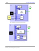
GTR64 http://www.matrix.es/GTR64 Figure 1. Main Blocks in a Wireless System (external micro-controller) Figure 2. Main Blocks in a Wireless System (embedded application) GTR64 Integrators Manual V.1.2 Pag. 8 Preliminary.
GTR64 http://www.matrix.es/GTR64 1.4 Main Features and Services The GTR64 performs a set of telecom services (TS) according to GSM standard phase 2+, ETSI and ITUT. The services and functions of the GTR64 are implemented by issuing customised applications embedded on the device, or by AT commands issued internally, or over the RS232 serial interface. 1.4.1 Types of Mobile Station The GTR64 is a a fully Quad Band capable GSM/GPRS mobile station with the characteristics shown in the table below.
GTR64 http://www.matrix.es/GTR64 1.4.4 Data The wireless modem supports the following data protocols: • GPRS (General Packet Radio Service) The wireless modem is a Class B terminal. The wireless modem is GPRS multi-slot class10 (4+2) enabled, capable of receiving at a maximum of four timeslots per frame (down link), and transmitting in two timeslots per frame (up link). See section 1.4.5 for multi-slot allocation by class.
GTR64 http://www.matrix.es/GTR64 2. MECHANICAL DESCRIPTION 2.1 Overview The pictures below show the mechanical design of the module along with the positions of the different connectors and mounting holes. The module case is made of durable PC/ABS plastic. Figure 3. GTR64 Module viewed from the right side Figure 4. GTR64 Module viewed from the left side GTR64 Integrators Manual V.1.2 Pag. 11 Preliminary.
GTR64 http://www.matrix.es/GTR64 2.2. Dimensions Figure 5. Dimensions of the GTR64 terminal in mm GTR64 Integrators Manual V.1.2 Pag. 12 Preliminary.
GTR64 http://www.matrix.es/GTR64 3. ELECTRICAL DESCRIPTION All electrical connections to the module are protected in compliance with the standard air and contact Electrostatic Discharge (ESD). The module uses the following industry standard connectors: • Sub-D 9 pin female (Main RS232 serial port) • High density 15 pin (Secondary RS232 UART and extended I/O interface) • RJ12 6-way (power supply connector) • RJ9 4-way (handset connector) • SIM card reader • FME male coaxial jack (antenna connector) 3.
GTR64 http://www.matrix.es/GTR64 3.2 Audio Conector A 4-way RJ9 connector, as shown below, allows a telephone handset to be plugged into the modem, giving access to the microphone and earpiece signals. The connector may also be used to drive other analogue audio sub-systems or devices. Although the GTR-64 is pre-configured to work with a range of handsets, the audio interface is flexible and its performance can be configured, using AT commands, to match a particular handset or audio subsystem.
GTR64 http://www.matrix.es/GTR64 The electrical characteristics are given in the table below. Parameter Input voltage full scale Frequency response Conditions Min Typ Max Unit RL = 30Ω 1.34 1.5 1.68 Vrms RL = 16Ω 1.41 Vrms RL = 8Ω 1.24 Vrms -3dB cut-off 300 3400 Hz Analogue audio can be used for various configurations, including a car kit mode, portable hands free and speakerphone (with an additional output gain stage).
GTR64 http://www.matrix.es/GTR64 3.4 Antenna Conector The antenna connector allows transmission of radio frequency (RF) signals between the modem and an external customer-supplied antenna. The modem is fitted with a 50Ω, FME male coaxial jack. Description of antenna connector parameters Parameter Limit Nominal impedance 50Ω (SWR better than 2.
GTR64 http://www.matrix.es/GTR64 3.6 RS232 Serial Port The modem supports a standard RS232 serial interface (EIA/TIA 574) via its 9 pin Sub-D connector, shown below. In line with serial communication terminology the GTR64 serial modem should be considered as the data circuit-terminating equipment (DCE) and the external application or computer as the data terminating equipment (DTE).
GTR64 http://www.matrix.es/GTR64 3.6.1 Serial Data The modem supports the standard data character format of • 1 start bit, 7 or 8 data bits, 1 optional parity bit, 1 or 2 stop bits • Programmable baud rate • Auto-configuration mode with auto-baud and auto-format operation In line with serial communication terminology the module is the data circuit-terminating equipment (DCE) and the external application or computer is the data terminating equipment (DTE). 3.6.
GTR64 http://www.matrix.es/GTR64 Data Carrier Detect (DCD) DCD indicates that the DCE is receiving a valid carrier (data signal) when low. You can define the exact behaviour of DCD with an AT command. Ring Indicator (RI) RI indicates that a ringing signal is being received by the DCE when low. You can define the exact behaviour or RI with an AT command. 3.7 Expansion I/O port The GTR64 supports a range of configurable I/Os including a second 2-wire RS232 interface.
GTR64 http://www.matrix.es/GTR64 10 RI1 IO 8 O I/O 0.4 – 3.2 V -0.5 - VREF Ring Indication Digital Input/Output I/O 8 11 IO 2 I/O -0.5 - VREF Digital Input/Output I/O 3 Digital VREF 12 IO 4 I/O -0.5 - VREF Digital Input/Output I/O 4 Digital VREF 13 SERVICE I -0.5 - +3.6V Flash programming enable signal Active High 14 GND 0V Ground connection 15 ADC 1 0 - 2.59V ADC Input 1 I 3.7.1. SECONDARY SERIAL PORT The secondary serial port is called UART3.
GTR64 http://www.matrix.es/GTR64 Clock synchronization can be used as a handshaking mechanism, to enable receivers to cope with fast data transfers. On a byte level, a slave (host application-side) I2C device may be able receive a data transfer, but need time to store the byte received before it is ready to receive another byte. The slave/receiver will therefore hold the SCL line low, after sending the acknowledge bit following the byte received, thereby forcing the master into a wait state.
GTR64 http://www.matrix.es/GTR64 All general purpose IO (GPIO) is programmable by the user. The I/O8 has alternate functionality already associated with it; this is indicated in the default column. This I/O which has alternate function is effectively multiplexed, so that the user chooses through AT commands the appropriate configuration for their application.
GTR64 http://www.matrix.es/GTR64 SERVICE Input Flash programming enable signal The SERVICE input signal is for flash programming enable input. The SERVICE pin is driven active high by the host application using either a logic control input or applying a dc voltage (common in legacy applications) to begin a flash download. This pin should be pulled leave unconnected during normal use Signal SERVICE Mode Active High Inactive Low Value Minimum input voltage 2.5 V Maximum input voltage 12.
GTR64 http://www.matrix.es/GTR64 Operating State LED Status After switching on the modem On after 4s Switch off (Power down) or power removed Off Standby or talk Flashing No network, network search, no SIM card, no PIN entered On Notes! Switch off (Power Down): DC power is applied but the modem is switched OFF. Standby: The GTR64 is switched ON and camped on to the network. No call in progress. Talk: The GTR64 is switched ON and a voice/data call is in progress. 5.
GTR64 http://www.matrix.es/GTR64 Code cannot be ported directly from an existing application and loaded directly onto the radio device. It must be re written in the Sony Ericsson Mobile script language so that the radio device interpreter can function correctly. 5.2.2 M2mpower IDE (Integrated Developers Environment) The IDE is a windows based package which allows the user to write, simulate, debug and download the application into a radio device with the embedded application (EA) software.
GTR64 http://www.matrix.es/GTR64 • The GTR64 Terminal must not be installed or located where the surface temperature of the plastic case may exceed 85°C. • All cables connected to the GTR64 Terminal must be secured or clamped, immediately adjacent to the modem's connectors, to provide strain relief and to avoid transmitting excessive vibration to the modem in the installation • Ensure the d.c. cable, supplying power to the GTR64 Terminal, does not exceed 3 metres.
GTR64 http://www.matrix.es/GTR64 IEEE (The Institute of Electrical and Electronics Engineers Inc.), through periodic and thorough evaluation of scientific studies. These guidelines establish permitted levels of radio wave exposure for the general population. The levels include a safety margin designed to assure the safety of all persons, regardless of age and health, and to account for any variations in measurements.
GTR64 http://www.matrix.es/GTR64 Tip! Before installing the modem, use an ordinary mobile telephone to check a possible location for it. In determining the location for the modem and antenna, you should consider signal strength as well as cable length. 7.1.3 Connections of components to GTR64 Terminal The integrator is responsible for the final integrated system. Incorrectly designed or installed, external components may cause radiation limits to be exceeded.
GTR64 http://www.matrix.es/GTR64 7.3.2 Antenna type Make sure that you choose the right type of antenna for the modem.
GTR64 http://www.matrix.es/GTR64 Following is an example of this, please visit www.matrix.es/GTR64 to see the full-range of accessories A) Power Supply GTR64 AC Power Adaptor: OPANIEL TECHNOLOGIES http://www.opaniel.com/ Input: 240VAC, 0.1A power adaptor, 50-60Hz mains lead Euro plug option. Output: 12V DC, 1.2A. 2m cable with RJ12 plug connector see below.
GTR64 http://www.matrix.es/GTR64 C) Right angle short antenna OPANIEL TECHNOLOGIES http://www.opaniel.com Model # MTX-ACODADA FME F D) Patch Adeshive Antenna OPANIEL TECHNOLOGIES http://www.opaniel.com MTX-UT902 – FME F 118.003.024 MTX- UT-902, RG174 3 mts, GSM DUAL BAND ( 900 / 1800 MHz ) ANTENNA Patch Antenna Cable RG174 3 Meters Gain 2 dB Frequency: 824-960 MHz, 1770-1880mhZ GTR64 Integrators Manual V.1.2 Pag. 31 Preliminary.
GTR64 http://www.matrix.es/GTR64 C) Expansion port - RS232 2-way Serial Cable Modem and System Breakout Cable 1m lead length with: • HD15 male connector Connected to; • DB9 female connector (9 signal RS232 serial connection) • 7 flying leads Conductor current rating < 1.
GTR64 http://www.matrix.es/GTR64 8. DISPOSAL OF OLD ELECTRICAL & ELECTRONIC EQUIPMENT (WEEE MARK) This symbol, applied on our products and/or on its packaging, indicates that this product should not be treated as household waste when you wish to dispose of it. Instead, it should be handed over to an applicable collection point for the recycling of electrical and electronic equipment.
GTR64 http://www.matrix.es/GTR64 10. AT COMMAND SUMMARY The AT standard is a line-oriented command language. AT is an abbreviation of ATtention and it is always used to start sending a command line from the terminal equipment (TE) to the terminal adaptor (TA). The command line consists of a string of alphanumeric characters. It is sent to the GTR64 to instruct it to perform the commands specified by the characters. The AT commands listed below are supported by the GR64(italic) within the GTR64.
GTR64 AT*E2CMGL AT*E2CMGR AT*E2EAMS AT*E2EMM AT*E2ESC AT*E2GAA AT*E2GC AT*E2GDV AT*E2IO AT*E2IPA AT*E2IPACT AT*E2IPATO AT*E2IPC IP AT*E2IPE IP AT*E2IPEV IP AT*E2IPI IP AT*E2IPL IP AT*E2IPO IP AT*E2IPRH AT*E2IPS IP AT*E2OTR AT*E2RESET AT*E2RS232 AT*E2SDR AT*E2SMSRI AT*E2SPN AT*E2SSCS _ AT*E2SSN AT*E2STKTO AT*EALS AT*EAUD AT*EBATTCNF AT*EBSE AT*ECAM AT*ECIND AT*ECLCC AT*ECSP AT*EDRX AT*EDST AT*EIDSUM AT*ELIN AT*EMBOX AT*EMIC AT*EMRDY AT*EMWI http://www.matrix.
GTR64 AT*ENAD AT*EPEE AT*EPIN AT*ERINFO AT*ERSE AT*ESIL AT*ESLN AT*ESRB AT*ESSE AT*ESTKMENU AT*ESTKRES AT*ESTKS SIM AT*TTY AT*USB AT+CACM AT+CALA AT+CALD AT+CAOC AT+CBC AT+CBST AT+CCFC AT+CCLK AT+CCWA AT+CCWE AT+CEER AT+CFUN AT+CGACT AT+CGANS AT+CGATT AT+CGCLASS AT+CGDATA AT+CGDCONT AT+CGEQMIN AT+CGEQNEG AT+CGEQREQ AT+CGEREP AT+CGMI AT+CGMM AT+CGMR AT+CGPADDR AT+CGRDATA AT+CGREG AT+CGSMS AT+CGSN http://www.matrix.
GTR64 http://www.matrix.
GTR64 AT+CSIM AT+CSMP AT+CSMS AT+CSNS AT+CSQ AT+CSSN tion AT+CSTA r AT+CTZU AT+CUSD AT+CVHU AT+GCAP AT+GMI AT+GMM AT+GMR AT+GSN AT+ICF AT+IFC AT+ILRR AT+IPR AT+VTD AT+VTS http://www.matrix.